The following section describes the development and the improvement of roll labelers that fundamentally changed the conventional labelers.
We are going to make the core technologies of the roll labelers in terms of the relationships with technologies both domestic and abroad.
- Table of Contents
- Trend of labelers in 1970s
- Development of a roll labeler
- Advantages of the roll labeler
- Core technologies of roll labelers
- Label cutting mechanism – Fixed blade & rotary blade type rotary cutter
-
Label infeed mechanism – Intermittent label infeed system
- One-way clutch type 2-crank intermittent roll label infeed mechanism (Patent; 1974.11) (U.S., U.K. and France, Patents: 1975)
- Ratchet type intermittent infeed mechanism (Patent Application:1979.6)
- One-way clutch type 2-crank intermittent infeed mechanismwith an over-rotation preventive mechanism (Patent:1979.7)
- One-way clutch type 3 crank intermittent infeed mechanism with a high speed infeed stop unit and a release crank (Patent: 1979.11) (U.S. Patent: 1980)
- Label tension adjusting mechanism
- Rotation driving control label table (Patent: 1975.12)
- Dissemination of roll labelerst
Trend of labelers in 1970s
First I am going to describe the trend of labelers both domestic and abroad in 1970s.
In Japan, SHIBUYA CORPORATION signed a technical partnership agreement with Morgan Fairest, U.K. for labelers in 1969 and started production by introducing the technologies of overseas companies. In 1970 abroad, Krones AG developed a label supply station (foliage label) employing a stick-on label take out system (
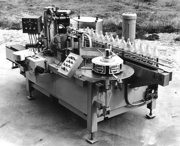
Figure below), B&H introduced a roll labeler (Photos below), and Accraply shipped tack labelers.
Though it is not about labelers, looking at conspicuous developments by automatic machine manufactures overseas, Sidel installed its first beer bottling line in 1971. The company started manufacturing labelers later. In Japan, Tokyo Automatic Machinery Works, Ltd. completed a cigarette wrapping line for the first time. In terms of trends related to labelers in Japan, Lintec started manufacturing and selling tack labelers in 1972 and, in the same year, Sansei Seiki started selling tack labelers for lipsticks. In 1973, EDM developed a tack labeler “LM-200 type” while Osaka Sealing Printing released tack labelers. In 1976, Sealex started manufacturing and selling tack labelers by Kugler-Womako.
Domestic companies did not develop their own labelers but produced products by introducing technologies from overseas companies.
As can be seen here, a lot of companies took part in, and have been engaged in the industry both domestic and abroad, irrespective of whether they developed products by their own. Numerous promising companies appeared when I think back those days.
In Japan, the major type was the tack labeler and only limited number of proprietary technologies were used in that type of labelers. What you should focus on above all is the fact that B&H started developing and selling roll labelers in 1970 when KOYO did start developing and selling them. Although detailed features are unknown, it is astonishing that some of the features employed in B&H’s products are the same as ours: suction drum, star wheel, and round finish plate. The company has shipped 2000 units of roller labelers alone until present.
Development of a roll labeler
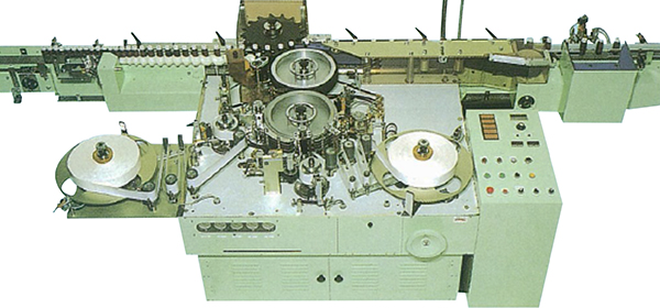
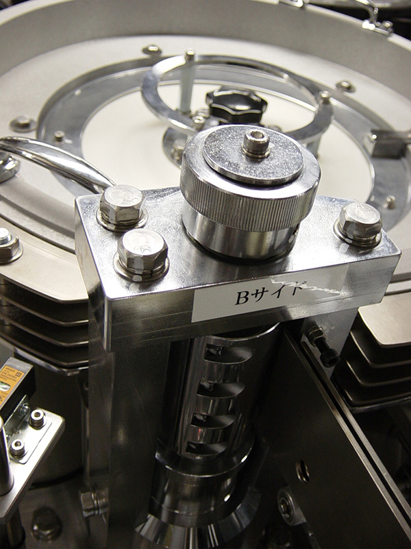
In the course of such trends, KOYO developed various models of hopper labelers one after another (LN-305, LK-300, LKKO, LRW) whose volume of shipments grew rapidly. That being so, the company proceeded with the development of a roll labeler with the intent to innovate the concept of the labeler(Photos and diagrams below).
Although the precise time when the development was started, the first patent application related to the roll labeler was made in 1974. For its important elements, the label cutter and the label infeed unit, patents were applied a fixed blade & rotating blade rotary cutter (Patent Application: 1974.8) and a 2-crank intermittent label infeed mechanism (Patent: 1974.11) in succession. In the next year, patents were applied for the latter mechanism in the U.S., France and the U.K. and granted (U.S., U.K. and France, Patents: 1975).
The company release its first intermittent label infeed type roll labeler “LRY-2000 (G company)” in 1975.
Advantages of the roll labeler
Then a question arises: Why did the chairman Yamashita embark on while the development of a roll labeler despite the growing performance of the company as a result of various hopper labeler models were developed?
This is because the company’s policy is to keep challenging without simply preserving the existing technologies or being satisfied with the present but looking to the future. Such passion for renovation inspired advantages to cut tape labels for pasting to containers. Small part of it is described in the patents (1974.8, 1974.11).
Then where does the biggest advantage of roll labelers lie?
Preventing intermixture with different types of labels
The advantage of roll labelers to name first is that it can prevent different types of labels from intermixing. A foliage labeler (hopper labeler) may allow intermixture with different types of labels when setting a lot of foliage labels (cut labels) in the hopper.
On the contrary, roll labelers cut a continuous roll label immediately before applying it to containers thus perfectly prevent intermixture of different types of labels. As a result, management of labels will be easier and human errors are prevented from occurring.
Leading speeding-up of production
The second advantage is that roll labelers support high speed operation.
Label application yield is about 150 per minute at most for foliage labelers (hopper labelers) while it is 200 to 800 per minute for roll labelers and the highest yield today is 1500 per minute, which means labels are applied to 25 containers per second.
What has made this high-speed operation possible is the fact that the operation of all of the label infeed and supply unit as well as the label applicator are rotational. This system does not require any reciprocating movements and performs quicker movement with minimum energy loss, which resulted in energy saving and higher efficiency of mass production.
Reduction of production cost
The third advantage is not only the reduction of production costs as a result of speeding-up and energy saving but also the considerable reduction of label costs.
The unit price of cut labels are higher than that of roll labels. Foliage (Cut) labels can become usable as labels only after they have done through processes to cut, align and set in the unit. On the contrary, roll labels, whether they are made of paper or films, printing is made directly onto the roll, which then will be rolled up to be a complete roll label. This means the unit price per label of a roll label is much lower. Even if a price difference per label is minimum, such price difference will accumulate in the course of mass production to become a huge difference and cannot be ignored.
Core technologies of roll labelers
Next section describes on the core technologies that enable roll labelers to have those advantages.
Label infeed mechanism
The first core technology to name is the label infeed mechanism.
Whether labels are fed properly or not depends on how a roll label printed at a certain pitch will be fed and cut according to the print pitch. Any roll labels have slight print errors or extension/contraction, which accumulate to cause a considerable cut error if the labels are cut at the even pitches. Label marks printed on a roll label, therefore, must be constantly detected on a sensor and resulting signals must fed back to adjust slight errors in label infeed at each session. In other words, infeed distances need to be lengthened or shortened slightly according to the print pitches. This is the innovative technology.
When there were no servo control unit, automatic and mechanical control was made possible for label infeed amount by detecting label marks and switching the clutch accordingly.
Label tension adjusting mechanism
The second technology is the label tension adjusting mechanism. This is related to how to reduce fluctuations in tension caused from infeed of roll labels.
Tension will change greatly when the label infeed speed changes suddenly due to the inertia of the roll set on the label table. As a result, extension or contraction of a label may lead to errors in transfer or might be torn.
This was solved with a mechanical mechanism equipped with a brake that is installed with the label table and operates in response to the movement of the tension roller arm.
Label cutting mechanism
The third is the label cutting mechanism. It supports highspeed label infeed with less energy and can maintain cutting efficiency of the cutting blade for an extended period of time. The challenge is how to realize a label cutting unit that withstands a vast number of cutting operations.
The fixed blade & rotary blade type rotary cutter called as “Hasami-giri, literally scissors-like cutting” has solved this. We will start with the description of the label cutting mechanism.
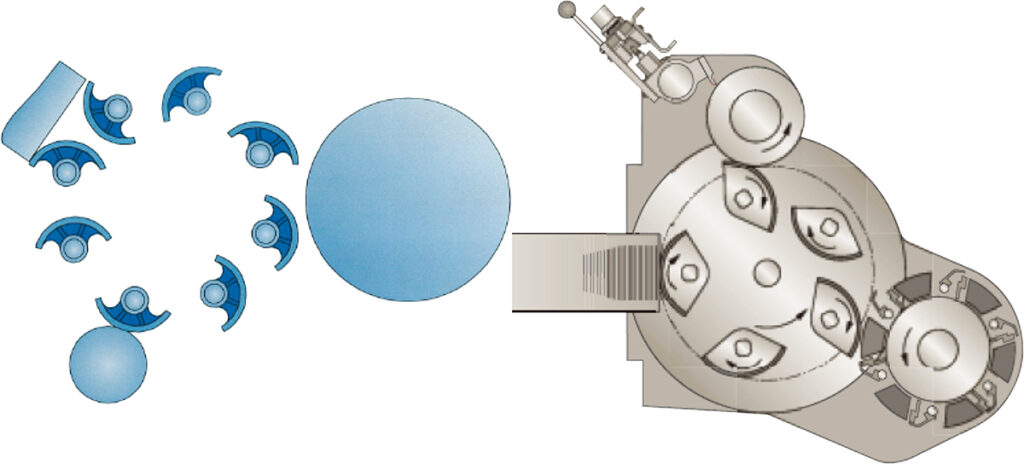
Label cutting mechanism – Fixed blade & rotary blade type rotary cutter
The older rotary cutters employed a system older than that of the fixed blade & rotary blade rotary cutter currently employed.
Each of elements that comprise a rotary cutter had already finalized at that initial phase. This system has been used for the rotary cutters for roll labelers for a long time since its development (Photos below). This rotary cutter is described in detail in the patent application “Cutter for tape, etc.” (Patent Application: 1974.8). The most prominent feature is that the rotary blade is installed slightly inclined onto the rotary blade drum. This is to cut a roll label in a motion similar to scissors when they cut a piece of paper (Figure below).
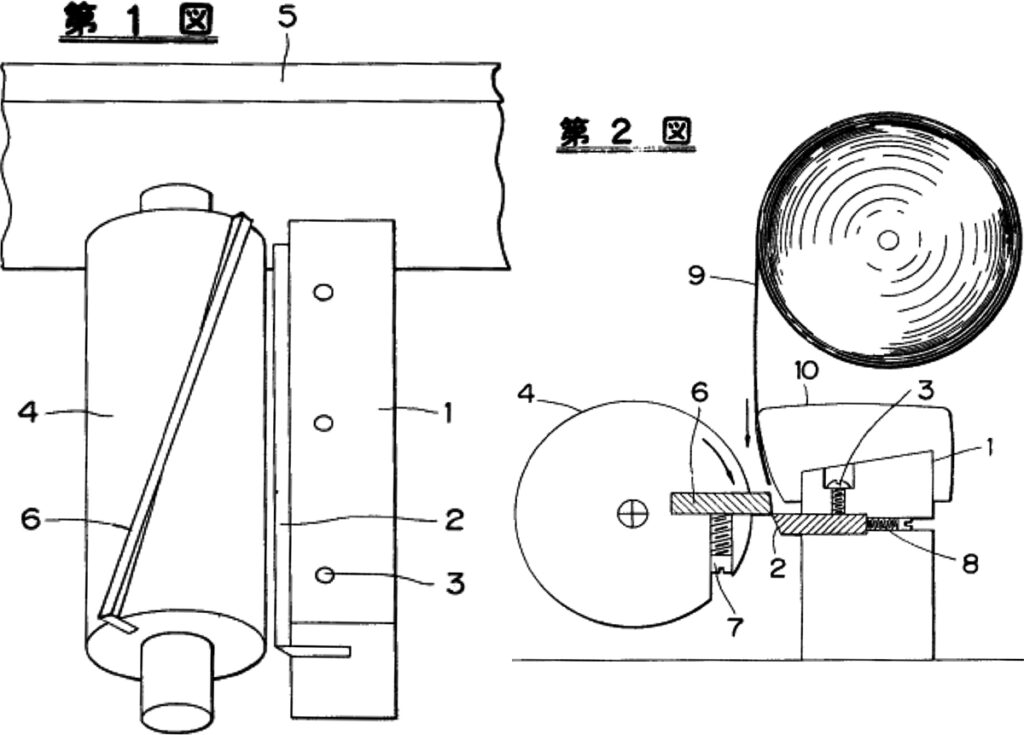
This results in the rotary blade always crosses with the fixed blade at only one point so that labels can be cut smoothly with minimum resistance. In addition, such smooth contact makes the rotary blade and the fixed blade grind each other with a grind stone to keep their cutting performance longer.
The guillotine cutting system was used in a lot of applications at that time, which system had disadvantages such as larger vertical movements or reciprocal movements causing a larger energy loss and the unit size was larger. On the contrary, rotary cutters employ rotating movement with less energy loss, allow to be a compact size and enable label infeed exceptionally higher. The first label infeed mechanism, however, was of intermittent label infeed.
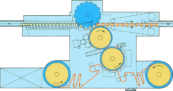
Label infeed mechanism – Intermittent label infeed system
Next section describes the label infeed mechanism.
One-way clutch type 2-crank intermittent roll label infeed mechanism (Patent; 1974.11) (U.S., U.K. and France, Patents: 1975)
The patent document “Tape infeed mechanism” (Patent Application: 1974.11), the first patent of a label infeed mechanism describes its mechanism in detail. The label infeed mechanism is of the intermittent label infeed system. This system repeats cycles that feed out roll labels at high speeds and then switch to feed out at lower speeds and then stop. While the infeed of the label is stopped, the rotary cutter cuts the roll label. This means that the cutting precision depends on how label infeed can be stopped at the precise position. This mechanism can be described in one word as: One-way clutch type 2-crank intermittent roll label infeed mechanism.
Such unique idea and wizardly mechanism are simply astonishing. The development of the rotary cutter and the one-way clutch type 2-crank intermittent roll label infeed mechanism seemed to be the nearly perfect mechanism. The company devised a new label infeed mechanism and continued improvement of crank type label infeed mechanisms to make label infeed speed higher and improve cutting precision while pre-empting market needs. I do not describe that development in detail here but some of them are indicated in the following patent documents.
Ratchet type intermittent infeed mechanism (Patent Application:1979.6)
This is a new intermittent infeed mechanism in which intermittent infeed is made by allowing the ratchet stopper claw to engage with one of the ratchet teeth inscribed in the rotation board. In order to improve the precision of the final stop position, only one of three stopper claws will engage with one of the ratchet teeth (i.e., precision equivalent to one third of the tooth pitch) and its stop and release are made using the swing ring and the swing unit.
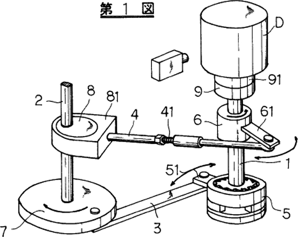
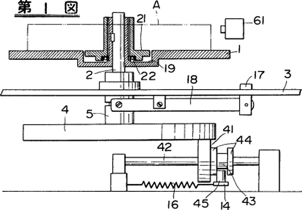
One-way clutch type 2-crank intermittent infeed mechanismwith an over-rotation preventive mechanism (Patent:1979.7)
This mechanism has been designed to increase intermittent label infeed speed, an improved version of the former described “One-way clutch type 2-crank intermittent infeed mechanism” (Figure 1 below).
The label cutting precision is determined depending on the precision of infeed amount for one label. This means that, in intermittent label infeed, the precision of the stop position is critical. In label infeed at a higher speed, stop positions might deviate from the inertia of the heavy drum (D). There is a one-way clutch type over rotation preventive unit installed directly below the main clutch (5).
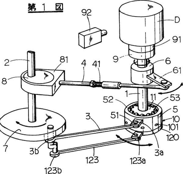
One-way clutch type 3 crank intermittent infeed mechanism with a high speed infeed stop unit and a release crank (Patent: 1979.11) (U.S. Patent: 1980)
This mechanism described here is the final version attained after repeated and continued improvements to further accelerate intermittent label infeed (2nd picture below).
In a higher speed intermittent label infeed, stop positions might deviate slightly even if the one-way clutch type over-rotation preventive unit described above (10) was activated. By installing a release crank (123) which releases that over-rotation preventive unit with minimum time difference, the stopping precision of intermittent label infeed was further improved.
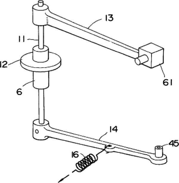
Label tension adjusting mechanism
This section describes the label tension adjusting mechanism. In order to reduce f luctuations in label tension, the amount to outfeed must be the same as that to be drawn out with the label infeed unit, or labels must be drawn out with their tension kept constant. In the former system, the driving label table send out labels in synchronization with the amount of label drawn out. In this case, the diameter of the roll label will be smaller as more labels are supplied to which the rotation speed of the label table needs to be increased gradually. The latter system takes out labels from the free label table by keeping the constant tension. In this system, rotation under the influence from inertia must be controlled on the label table according to the changes in label drawing out speed.
Rotation driving control label table (Patent: 1975.12)
Shown here is the system for sending out labels with the driving label table shown as the former example (
Figure below).
A signal will be issued when labels are supplied and the roll diameter becomes smaller and the distance between the outer surface of the roll (4) and the sensor (61) reaches the certain amount. This signal releases the solenoid brake (6) so that the detection arm (13) swings toward the label roll and the driving wheel (41) that is in contact with the driving table (4) moves inward. This results in increased rotation of the label table to keep the lengths to be sent out constant. The theory described in the patent lead to the label send out control method using a servo motor currently employed.
It is also very interesting that this method also attempts to perform servo control mechanically.
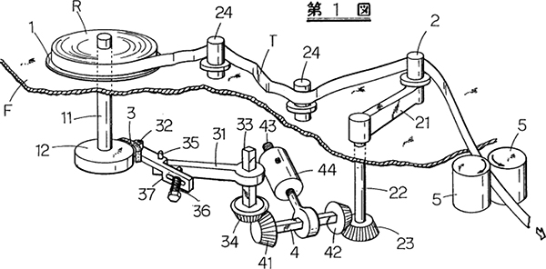
Tension arm type label table (Patent Application: 1980.8)
These figures show a mechanism that controls fluctuations of tension to draw labels from a free label table (Figures and photos below).
The tension arm (21) of the guide roller (2) oscillates in response to increase or decrease in tension of roll label (R). In tandem with this movement, the brake shoe (3) comes in or off contact with the friction disk (12) to control the rotation speed of the label table. If label tension increases to cause the tension arm to swing toward the label table, the brake shoe will come into contact with the friction disk to apply brake to decelerate the label table. On the contrary, if label tension decreases making the tension arm moves away from and comes off the label table, the brake will be released. These actions are repeated instantly to control fluctuation in label tension.
This mechanism had been adopted in the old type roll labelers for a long time. After that, development and improvement of core technologies for roll labelers were never stopped including the label infeed mechanism, the label tension adjusting mechanism or the label cutting mechanism. The label tension adjusting mechanism, for example, uses a roller type label table to minimize inertia or friction braking using a powder brake (Patent Application: 1991.5) as its core technologies. Likewise, a series of new technologies were developed for the label infeed mechanism and the label cutting mechanism as will be described later.
Dissemination of roll labelerst
At that time (1974), label manufacturers did not produce roll labels, which were not available in the market. It is said that printing machine for roll labels had to be made. And label rolls were made by wrapping roll labels printed on roll paper around a paper core.
The roll label was created for the first time in Japan through those efforts. And it seemed to take a long time for the roll labelers to disseminate. Interestingly there was an episode that the company taught how to print roll labels to a label maker to tell how wonderful roll labelers were.
We could establish sales routes by joint efforts with label manufacturers and roll labelers were disseminated. Chairman Yamashita says: “It is difficult for us to do all businesses by the company alone, instead new demands can be cultivated by moving through the way of co-existence and co-prosperity with companies of different business fields.” He continues, we can’t say “All we have to do is to manufacture good products, which will sell well simply because they are good”. Customers will make profits by using such good products, companies of different business fields can sell their own products and make profits with those products, and consumers feel satisfied with products manufactured using those products. This must mean, we have to do business in such a way that “all win (all become happy)”. Such policy is the same as the principle of old Japanese Ohmi Shonin (Ohmi-district merchants), “Sanpo-Yoshi (satisfying all three parties)”, which translates as good to the seller, the buyer, and society.