Chairman Yamashita, confronted with the fact that the patents for roll labelers expired one after another before and after 2000, started development of a new roll labeler in 2003 by pre-empting 10 and 20 years after. He forgot a serial of technologies for roll labelers once and produced new technologies almost successively.
At that time interests were growing for cost reduction and environmental issues, shifting to ultra-thin label films was pursued. In the beverages industry, for example, the thickness for PET bottles became thinner from 50μ to 30μ or less, which made label infeed difficult. Another problem was ever thinner PET bottle side walls, which caused a challenge of labeling to easily squished bottles for the labeling industry. Given these challenges, efforts were started for drastic improvement of each of comprising elements of a series of roll labelers and development of a new mechanism.
The first example of such efforts was the development of a rotary cutter of a movable fixed blade with an angle adjustable function type (swing type) and the completion of a prototype model. Based on the prototype, the label infeed assembly was completely renewed and improved in multiple phases by repeating label infeed and cutting tests to finalize a new mechanism. Resultant mechanisms included: a roller boss type label table, a supplementary infeed buffer conveyor type label infeed mechanism and a tension arm control type label infeed mechanism. These mechanisms enabled high-speed switching between high-speed infeed of ultra-thin films and the label infeed unit, thus the pasting speed and the efficiency of roll labelers increased one step higher.
These technologies were incorporated in actual machines and worked as a main drive for the development of a new model of a wrap-around film labeler for rectangle containers. In addition, these technologies indicate a direction of further development of a roll shrink labeler.
Development of a new rotary cutter
Conventional label cutters have long been employing a fixed blade & rotary blade type rotary cutter.
Remodeling of rotary cutters, however, was needed because higher skill is necessary for adjusting the fixed blade and the operation speed of the machine must be reduced considerable when replacing the label supply unit.
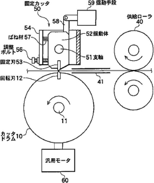
Movable fixed blade with an angle adjustable function type (Patent: 2003.12)
By changing the conventional fixed blade to movable blade type, instantaneous switching of label supply sides was enabled. It was made possible to adjust the inset/outset of a cutter blade when it is worn simply by pushing in or pulling out the adjusting bolt that has a role of the fixed blade stopper as well. Thanks to the elasticity of the fixed blade movable body, cutting is made smooth as well as cutting efficiency is kept longer from the sharpening effect that occurs between the fixed and the rotation blades (Figures and photos below).
Movable fixed blade type with a suctioning function (Patent Application: 2004.1)
This type suctions labels at the suction port made in the rotary cutter drum to transfer them to the transfer drum to enable transfer of labels to the suction drum when cutting long labels.
Air blow movable fixed blade type (Patent Application: 2006.3)
This type blows pressurized air at the air blow nozzle made before the cutter to prevent label infeed jamming immediately before the cutter blade.
New label supply unit
Then development phase proceeds from the development of a new label cutter to that of a label infeed unit, which is located in the upstream side of the label infeed. An innovative idea never seen before to remodel the label table to completely redesign the label infeed mechanism.
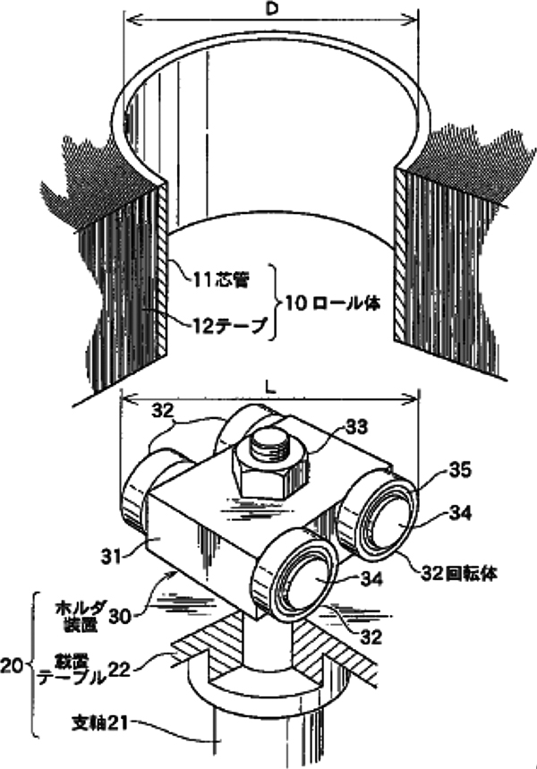
Roller boss type (Patent: 2005.3)
Using a holder with a roller on the label table, the roll body of a roll label can be inserted and fixed in and to the label table simultaneously.
In conventional systems, a roll label must be locked with a pin or other means after the label was set to the label table. By employing this system to the automatic roll label supply unit described above, it has become easy to set a roll label to the label table automatically (Figures and photos below).
Roller boss type with a braking friction plate (Patent Application: 2005.11)
This type changes braking force in proportion to the weight of a label roll by installing a braking friction plate immediately under the label table above.
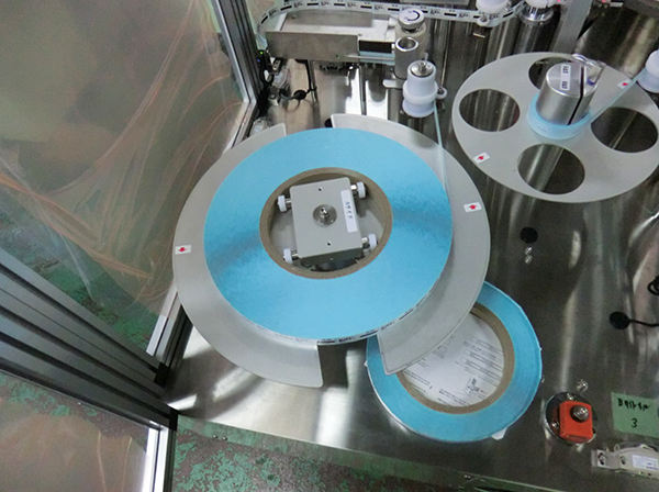
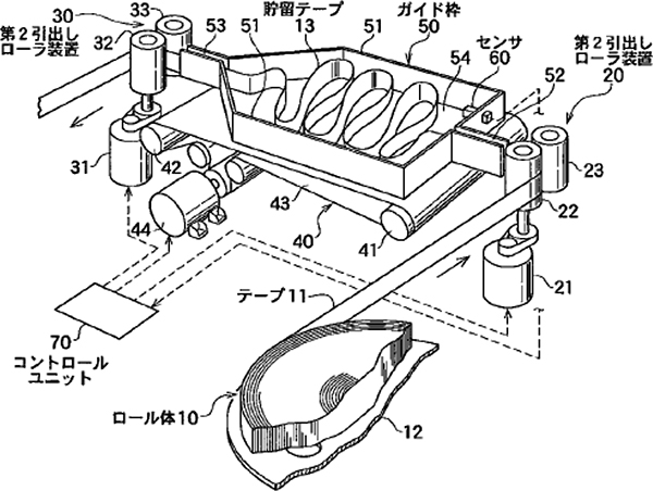
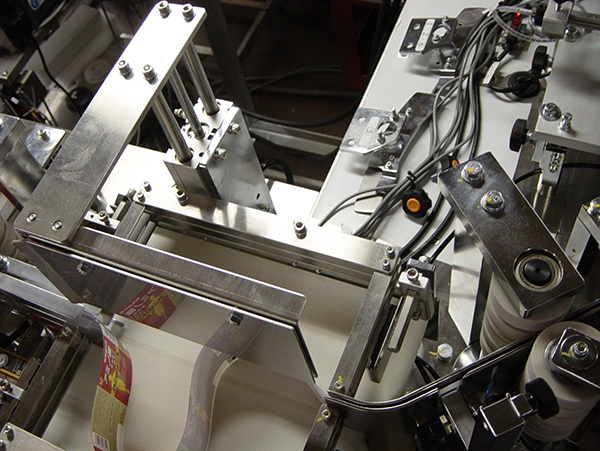
Supplementary infeed buffer conveyor type (Patent Application: 2005.10)
Roll labels will be drawn out from the No.2 take-out roller unit (supplementary infeed assembly) to the buffer conveyor (40), where the roll labels will be pooled so that any label tension will not be generated at the No.1 take-out roller unit (label feed assembly). This prevents extension of a roll label made of an ultra-thin film and enables precise cutting (Figures and photos below).
Tension arm control type label infeed mechanism (Patent Application: 2010.12)
It may look like a product quite similar to the conventional tension arm type label table described before.
This label infeed mechanism has a label table equipped with a servo motor driving source to infeed labels to be consistent with the amount of a label taken-out by detecting a mark.
The table rotation speed is determined as the first-order approximation by calculating from the roll diameter determined by measuring the distance to the outer periphery of the roll using a label diameter measurement sensor. Label taken-out amount will slightly increase or decrease depending on printing errors or label extension or contraction. To cope with such subtle increase or decrease in speed, the swing angle of the tension roller arm is detected on which arm labels are hanged, take-out amount obtained with the servo motor on the table so that tension on the labels will be kept at the minimum. When switching the label supply units, take-out speed will decrease so that labels will be pooled on the tension roller to enable smooth transition to the supply starting unit.
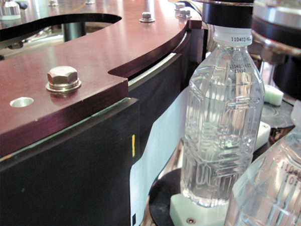
Wrap-around roll labeler
To meet ever increasing demand for labeling to PET bottles, development of a roll labeler became an urgent task to support various shapes and sizes from round to rectangle or small to large as well as to enable ultra-thin films to be wrappedaround light weight bottles. It is, of course, a minimum precondition for labels that they will not peel off during boxing, transportation, displaying at a store or when taking out from an automatic vending machine. On the contrary, specifications required for labels include adhesives that will not remain on containers and labels can be peeled off easily for ease of recycling.
And in production plant lines that higher efficiency is required, labelers must have a performance or durability that can withstand harsh operating conditions such as a 24-hour operation. As a result, we had to solve challenges to automatically supply roll labels in stock for setting or to smoothly and quickly switch between two label supply units automatically. Such challenges extended to various fields: the employment of a servo motor for rotation of a base cup for a turret rotary system, remodeling of the application drum system, and label gluing systems such as heat sensitive labels, hot melt or a UV curing adhesive (“Shrink label gluing method using UV curing” Patent: 2010.7).
Wrap-around label application drum (Patent Application: 2006.8)
A “relief part” is ensured on the periphery surface around the application drum to wrap labels around rectangle containers that are carried on the turret rotary while being rotated.
The relief part ensures smoother wrapping-around of labels while preventing rectangle containers that rotate while revolving from coming into contact the application drum.
Wrap-around label & relief shape application drum (Patent Application: 2007.6)
In addition to ensuring a “relief part” to the periphery surface around the application drum to paste wrap labels around rectangle containers as well as an “interim supplementary part” to supplement a label adsorption length of a label.
This allows quick and precise wrapping-around of a wrap-around label to rectangle containers that rotate while revolving.
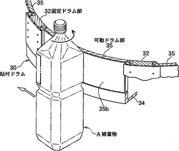
Wrap-around label & movable application drum (Patent: 2008.1)
A movable drum assembly that moves forward/backward is installed on the periphery surface of the application drum to prevent rectangle containers that rotate while revolving from coming into contact the application drum during wrapping and application processes of wrap-around labels around rectangle containers.
This allows quick and precise wrapping-around of a wrap-around label to rectangle containers that rotate while revolving (Figures and photos below).
Wrap-around label & Leading/trailing edge pads type application drum (Working example 2011)
An adhesive is applied to the leading and trailing parts of a label to be suctioned with the application drum for transfer so that the leading edge of the label is adhered to a container transferred to the turret rotary while revolving. Immediately after this, containers rotate at a high speed to make a label wrap-around and the trailing edge of a label overlaps the leading edge of the same label and glued together (Photos below).
This wrapping operation takes advantage of the rotation motion concept for label application using an “application drum” and an “R finishing plate” that pastes labels to containers by making them rotate while revolving. The motion of wrapping and pasting labels has been attained with simple operations rotation and revolution, which enables to wrap a label precisely around the whole periphery of a thin easy-to-squish PET bottle.
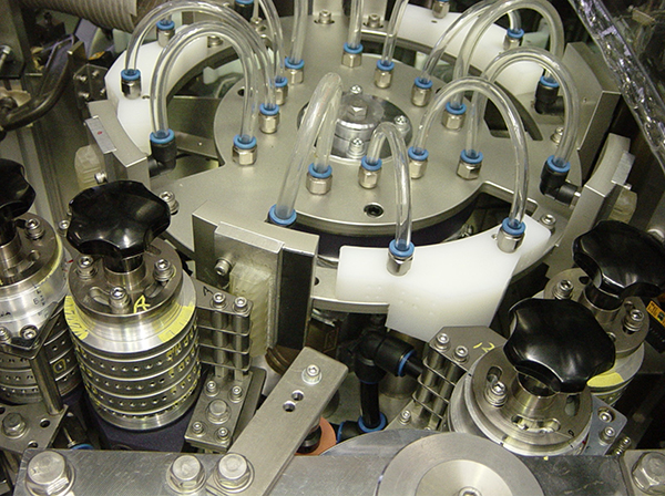
As described in these sections, roll labelers have been improved their performance through a many development phases until now for these 39 years since we started the development.
To looking back the history of the roll labeler, the first was the intermittent infeed mechanism, which developed to a continuous infeed mechanism, and over several technologies such as the automatic label supply switching mechanism, the punching unit, and the pasting system for a high-speed roll labeler, the technology has completed as the present roll labeler (Photos below).
These technologies were disseminated outside Japan, to a lot of countries in the world and now they have adopted as the world standard technologies. For appraisal of those achievements, Mr. Kyoichi Yamashita, the Chairman of the company was awarded “The Prize of the Director-General of the Science and Technology Agency” in 1986 and “The Medal with Yellow Ribbon” in 1996. In the year of 2003, as described at the beginning of this section, the company once forgot core technologies established and attempted to reestablish a new roll labeler, which led to the completion of a roll labeler incorporated with innovative technologies. It seems that there is no “completion” with any satisfaction not only in the technology but also in the field of making things. We have always been sticking to that principle, working on sites to follow changes in time or needs, and stepping out of our own technologies, which have resulted in technological innovations whose influences have disseminated and will disseminate.