In process of speeding up label infeed, an idea seemed to have been born that the method to cut labels by repeating high-speed infeed and stop (intermittent label infeed mechanism) shall be abandoned and drastic acceleration of cutting may be possible by employing the continuous label infeed system.
In the next year (1980) of the year when the final system of an intermittent label infeed mechanism was completed, a lot of patents for rotary cutters that support continuous infeed or their mechanism were applied for one after another.I cannot but respect all parties who pre-empt market needs, try to improve the quality of products and never stop developing new products despite the fact that completely newly developed and perfected a series of products were sold well. I am going to show brief overview of those patents to present some of key contents of them.
- Table of Contents
- Label cutting mechanism that supports continuous label infeed
-
Continuous label infeed mechanism
- Pressure roller switching type (Patent: 1980.2, Patent: 1980.4)
- Dual infeed type with drums facing each other (Patent: 1980.5.16, Patent: 1980.5.30, U.S., Taiwan, South Korea Patents: 1981)
- Additional variable diameter drum driving type (Patent Application: 1980.6.5, Patent: 1980.6.23, Patent: 1980.7.2, Patent: 1980.7.14, Patent: 1980.7.25, Patent: 1980.8, U.S. & Taiwan Patents: 1981, U.S., Taiwan, and South Korea Patents: 1981, Patent. 1981.6, etc.)
- Variable speed driving gear switching type(Patent: 1981.10, Patent: 1981.11, Patent Application: 1982.3, Patent Application: 1982.3, Patent Application: 1983.2, Patent Application: 1983.7 [Final version], U.S. & Taiwan, Patent: 1985)
- Devisal of the automatic label supply switching system
-
Introduction of a label punching unit
- Swinging “Scissors cutting” type (Patent Application: 1981.6)
- Concave and convex blades type (Patent Application: 1983.8) (U.S., France, and U.K. Patents: 1984)
- Punching-after-cut system, label supply switching system (Patent Application: 1984.1) (U.S. and South Korea Patents: 1985)
- One way operation drum for 2-face pasting for front/back of punched labels (Patent: 1985.1)
- Receiving blade drum transfer system (Patent: 1986.4) (U.S., U.K., and Germany Patents: 1987)
- Bearer holding type: Final version (Patent: 1986.8)
- Scrap processor, compressing process of punched label scrap(Patent: 1985.1)
- Development of an automatic roll label supply unit
- High speed application system
Label cutting mechanism that supports continuous label infeed
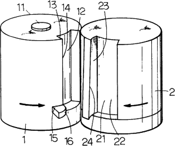
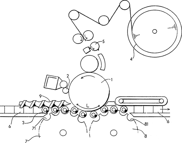
The company has developed a rotary cutter “Dual rotating blade rotary cutter with a guide claw (16)” that supports continuous label infeed which cutter is equipped with 2 rotating blades (1 & 2) facing each other, for which the patent was granted (1980.4).
This product was developed to overcome the drawbacks of the fixed-blade and rotary blade type rotary cutter such as a troublesome adjustment of the fixed blade or having to pause label infeed for certain procedures (Figure below).
Continuous label infeed mechanism
During this period, the company was active in development of several label infeed mechanism along with the development of rotary cutters that support continuous label infeed. It is astonishing that patent applications related to continuous label mechanisms counted to over 20 for only 4 years between 1980 and 1983.Because of the limited space, I cannot refer to all of them and describe such mechanisms that characterize such developments.
Pressure roller switching type (Patent: 1980.2, Patent: 1980.4)
The type is equipped with a highspeed driving drum (2) and a low speed driving drum (3) whose perimeters differ slightly and controls the label infeed speed by switching the pressure rollers (4 & 5) on the high-speed and the lowspeed sides in response to signals from the photoelectric tubes (R1 & R2) that detect label pitches. The infeed drums have slits, whose gaps are changed to control the infeed speed (Figure 1 below).
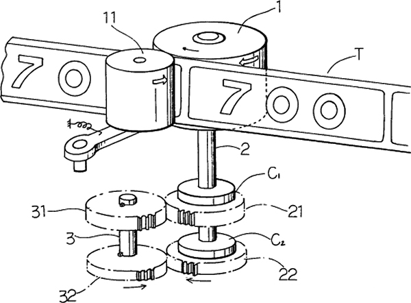
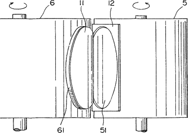
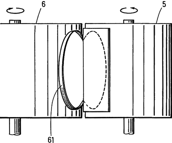
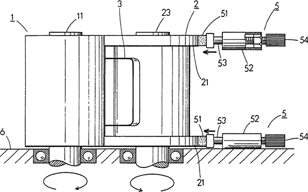
Dual infeed type with drums facing each other (Patent: 1980.5.16, Patent: 1980.5.30, U.S., Taiwan, South Korea Patents: 1981)
This type transfers driving force to the long perimeter infeed drum (3) via an electromagnetic clutch and to the short perimeter drum, via a 1-way clutch. It controls label infeed by repeating long perimeter infeed and short perimeter infeed by switching the electromagnetic clutch (2nd picture below).
Additional variable diameter drum driving type (Patent Application: 1980.6.5, Patent: 1980.6.23, Patent: 1980.7.2, Patent: 1980.7.14, Patent: 1980.7.25, Patent: 1980.8, U.S. & Taiwan Patents: 1981, U.S., Taiwan, and South Korea Patents: 1981, Patent. 1981.6, etc.)
In addition to label infeed control by switching the long perimeter drum and the short perimeter drum with a signal, small difference in rotation driving force is controlled depending on increase and decrease in the diameter of the variable diameter drum by receiving the driving force from the variable diameter drum that changes with the same signal. The system established a highly accurate label infeed mechanism (Figure below).
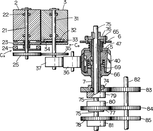
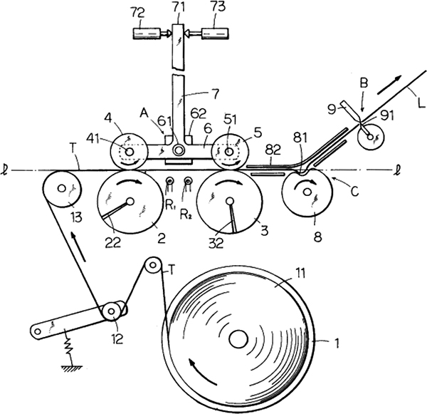
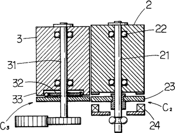
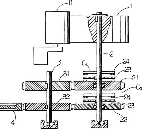
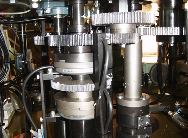
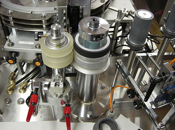
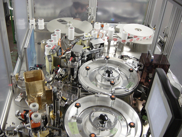
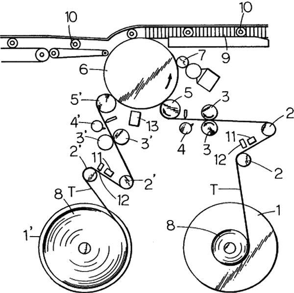
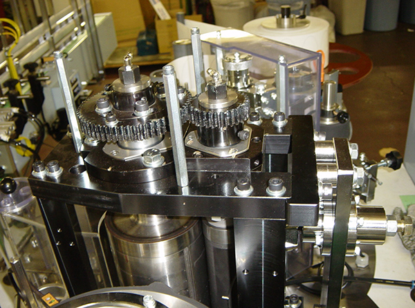
Variable speed driving gear switching type(Patent: 1981.10, Patent: 1981.11, Patent Application: 1982.3, Patent Application: 1982.3, Patent Application: 1983.2, Patent Application: 1983.7 [Final version], U.S. & Taiwan, Patent: 1985)
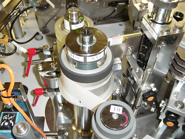
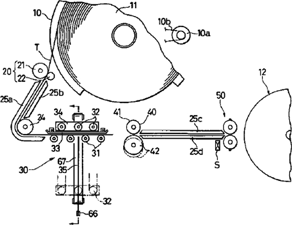
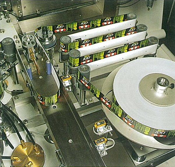
This system controls label infeed by repeating long infeed and short infeed by pressing the pressing roller (11) against the label infeed drum (1) to switch the electromagnetic clutches (C1 & C2) for the deceleration gear (21) and the acceleration gear (22). It feeds a label tape at the constant pitch to the printed information on it. When product types shall be changed to a different label length after product types are changed, the drum will be replaced with the infeed drum for the new product type (Photos and diagrams below).
We can tell from the historic trends of continuous label infeed mechanism above that a mechanism to control increase or decrease a small label infeed distance has been established gradually while a variety of ideas and their realization have been attempted in order to make label infeed more precise.
The continuous label infeed unit has solved a challenge difficult to solve from a perspective of mechanical aspect to draw out tape labels continuously with a simple system. This has been installed in roll labelers for a long time together with fixed-blade and rotary blade type rotary cutters.
To put the cutting position of a roll label close to the specified position, label infeed amount will be controlled by repeating switching of the large infeed gear and the small infeed gear using the electromagnetic clutch for the driving gear of the label infeed drum. A rotary cutter to be connected to that driving system will be connected to the main unit driving assembly when it detects a container, the pin removal arm will be disengaged from the pin clutch causing the connecting pin is inserted into the pin hole. This starts the rotary blade drum of the rotary cutter to cut the roll label into the constant width. If the cutter does not detect any containers, the pin removal arm is inserted into the pin clutch body to shut off driving so that the rotation of the rotary blade drum will stop. The whole system carries out label infeed and label cutting simultaneously by being organically linked to a series of driving systems so that precisely cut labels will be applied in succession at a high speed to containers which are transferred one after another. I feel as if I’m watching some magical techniques.
Devisal of the automatic label supply switching system
While the company has been thinking of and commoditizing various continuous label infeed mechanism in succession, it has also been devising a series of automatic label supply switching systems to enable continuous operation (from June 1980 to June 1984).
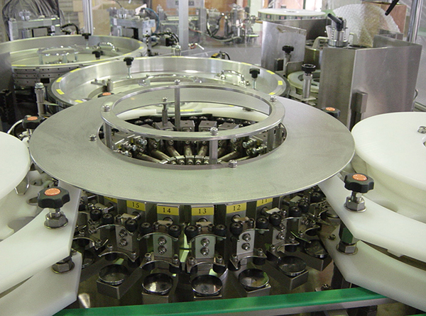
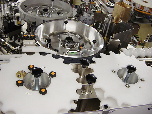
The system feeds roll labels to set and done not need the related machines and equipment to stop operation. When the label supplier (the label table, the label infeed unit and the label cutter) is integrated in one unit, the labeler stops operation when the current roll label currently on the label table runs out and a new roll label must be set on the line from the label table to the label cutter. The line will stop during this procedure and a lot of containers will accumulate on the upstream conveyor belt. As a result, a long conveyor belt needs to be installed to accept accumulating containers. Production efficiency will dramatically improve if continuous operation is possible without having to stop labeler operation. In addition, the line can be designed to be compact, thus capital investment in plant and facilities can be reduced. Considering these advantages, 2 label supply units were installed in a roll labeler, one of which units automatically start supplying labels when the other finishes supplying labels to avoid stopping labeling processes (Photos below).
Many technical challenges arise one after another about how to switch label supply automatically without causing any troubles and compromising the operation speed. Here some of such technologies from patent documents.
Label supply unit system (Patent: 1980.6, Patent: 1980.7)
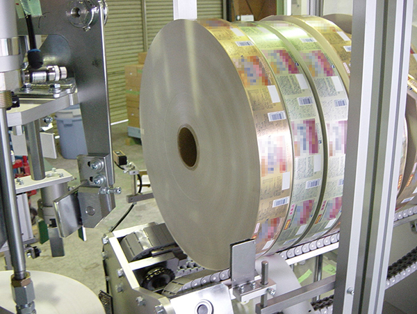
Two supply units from the label table (1) to the suction drum (5) will be installed, when the end of the roll label of the first (No.1) unit is detected (11), the second (No.2) unit starts operation and the No. 1 unit stops. Roll labelers of the company have been employed this system until present (Figure 1 below).
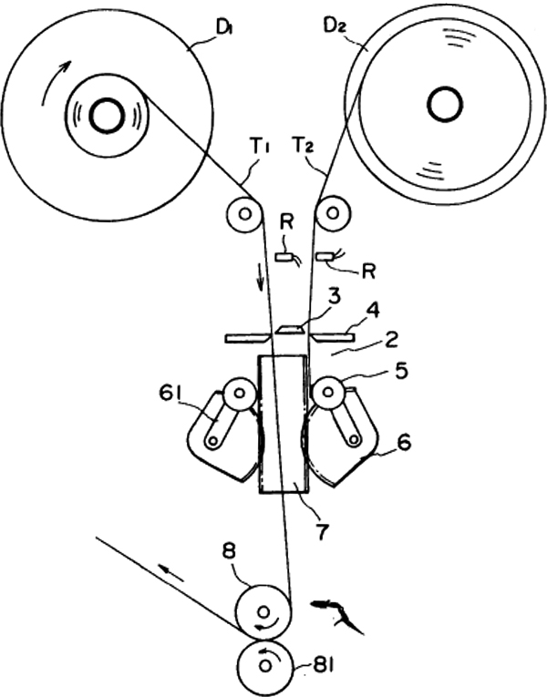
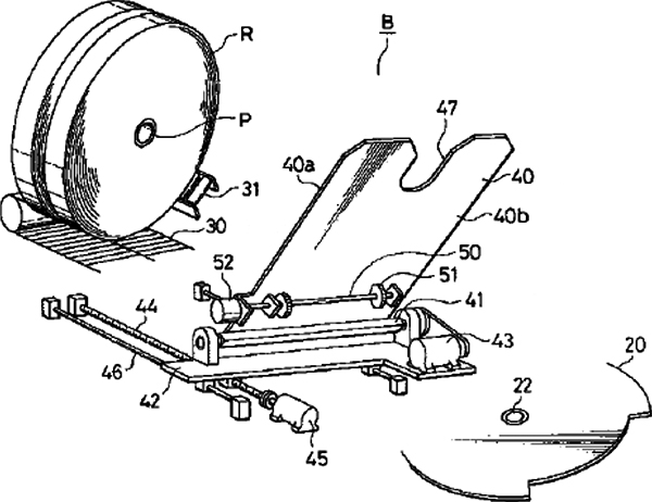
Automatic tape joining system (Patent Application: 1982.4)
Two label tables (2) are installed, when it is detected that the roll label for the No.1 unit has run out (R), to the end of which the adhesive leading edge of the roll label of the No.2 unit is pressed to joined, unnecessary portion is cut off (3 & 4) to enable successive label supply. Krones AG (Germany) and other companies have adopted and used until now (2nd picture below).
Krones AG introduce a roll labeler for the first time in 1985, about 10 years since KOYO developed a roll labeler (July 1975). It was the next year of the year Krones AG opened up an affiliate in Japan (1984). The automatic label supply switching system then was quite similar to the KOYO’s automatic label joining system (Patent: 1982.4). And in terms of the label application system, a vacuum suctioning application drum was adoptedwhich was the first system for Krones AG.
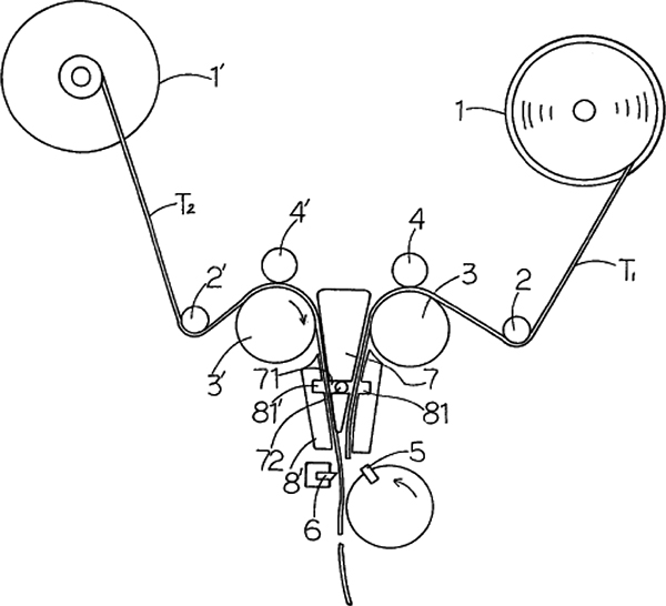
Uncut label infeed switching system (Patent: 1983.5, Paten: 1983.7)
This system has 2 sets of supply units comprising from the label table to the label takeout roller for 1 unit rotary cutter. When the end of the roll label of the No.1 unit is detected, the No. 2 unit starts operation when that end is aligned with the leading edge of the roll label of the No. 2 unit, and, at the same time, the No.1 unit stops its operation. This system automatically switches supply of roll labels using a unit that instantly moves back the leading edge of a roll label (Figure 1 below).
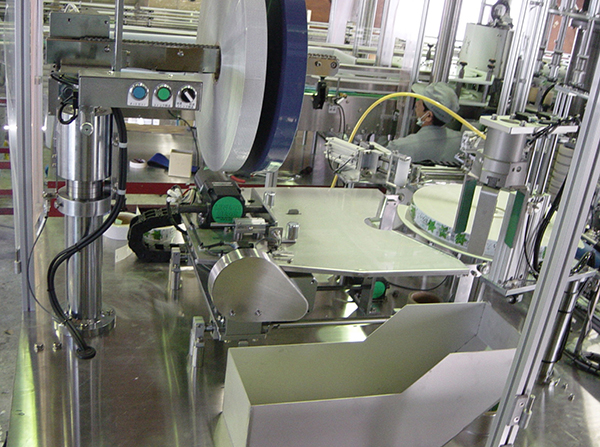
Label supply unit system with label punching function (Patent: 1984.6)
This system has 2 sets of supply units comprising from the label table to the label application drum with label punching function, when the end of the roll label of the No. 1 unit is detected, the No. 2 unit starts operation and the No.1 unit stops its operation.
Its main feature is that the standby supply unit will start operation automatically even if a roll label is broken (2nd picture below).
Introduction of a label punching unit
During the period from 1981 to 1986, development of a system was proceeded with to continuously punch undefined shaped labels from a roll label and which development evolved into a complete punching unit. It employs a rotary cutter to cut a roll label into rectangles at a constant pitch, punches into undefined shape labels (such as an oval) with the punching unit and then the application drum pastes them to containers.
The first roll labeler which was integrated with a label punching unit (LR-**P) was shipped in 1984.
Swinging “Scissors cutting” type (Patent Application: 1981.6)
This system is a roll label punching unit that uses a cutter and a receiving blade having a “scissor cutting” effect by swinging motions. It does not cut roll labels into rectangle shapes with a rotary cutter.
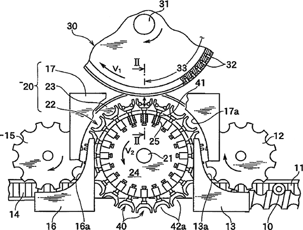
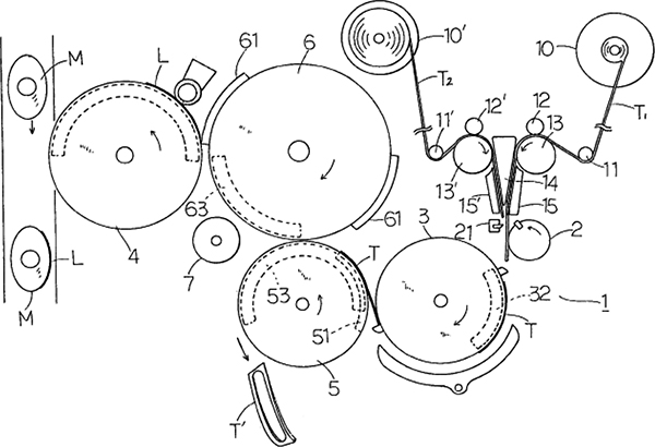
Concave and convex blades type (Patent Application: 1983.8) (U.S., France, and U.K. Patents: 1984)
After the rotary cutter cuts a roll label into rectangle shapes at a constant pitch, those labels are punched into an undefined shape (such as an oval) with the punching unit and then the application drum pastes them to containers. Cutting labels into rectangles before punching enables punching at the minimum label pitch. Scrap paper is suctioned, transferred and discharged for process and there is no need for a collecting unit to roll up waste tapes as for the conventional systems (Figure 1 below).
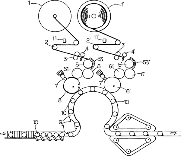
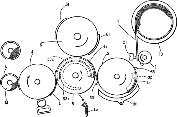
Punching-after-cut system, label supply switching system (Patent Application: 1984.1) (U.S. and South Korea Patents: 1985)
These systems are equipped with an automatic uncut label supply switching system (Patent: 1983.7) to the aforementioned (Patent: 1983.8) roll labeler with a punching unit so that continuous supply of labels is possible.
These systems also suction, transfer and discharge scrap paper and do not require a collecting unit to roll up waste tapes needed for conventional systems (2nd picture below).
One way operation drum for 2-face pasting for front/back of punched labels (Patent: 1985.1)
One piece of label is cut out of the roll label for front and back labels, where the punching unit cuts 2 labels, for front and back. The slide suction head at the application drum moves labels to the specified pitch and then pastes them to the front and back surfaces of containers.
Receiving blade drum transfer system (Patent: 1986.4) (U.S., U.K., and Germany Patents: 1987)
This system cuts a roll label into rectangle shapes at a constant pitch with the rotary cutter, punches them into an undefined shape (such as an oval) with the punching unit and then the application drum pastes them to containers. Cutting labels into rectangles before punching enables punching at the minimum label pitch.
The receiving blade drum transfers punched labels and scrap paper, then the punched labels will be transferred to the pasting drum while the scrap paper will be transferred to the discharge assembly. This system comprises the final layout and is different from those referred to in the series of patent documents.
This system suctions, transfers and discharges scrap paper and does not require a collecting unit to roll up waste tapes needed for conventional systems (Figure below).
Bearer holding type: Final version (Patent: 1986.8)
This type is a punching unit comprising an anvil drum and a die drum, holds the bearer assembly of the die drum with a polishing unit with whetstones so that operation can be continued even if the die cutter blades are worn (Figure below).
Scrap processor, compressing process of punched label scrap(Patent: 1985.1)
Scrap paper generated at a label punching unit is rolled up with two rotating rollers, compressed to reduce volume.
Development of an automatic roll label supply unit
We had to develop this unit under the circumstance below. Shifting to a high-speed mass production at our plant lines,which required frequent setting of roll labels and increased workers’ burden. If multiple roll labels could be kept in stock, roll labels could be supplied to the table automatically and from the table, they could be set through the draw-out roller to the cutter automatically, the workers should no more need to monitor one labeler constantly.
Tray type automatic supply unit (Patent: 1994.12)
This unit stocks two or more label rolls on the conveyor belt (hanged with a stocker equipped with a transfer chain in the present system), hands them over onto the tray, set them by laying them down on the table and then sets them automatically up to the rotary cutter. Setting to the label table can be made by unmanned operation to save energy and shorten work time greatly (Figures and photos below).
Automatic roll label setting unit (Patent: 1995.7)
This unit is equipped with 2 rollers, a fixed roller and a movable tension roller and can automatically set roll labels by shifting the movable roller after labels have passed it.
By installing this together with the aforementioned automatic roll label supply unit, labels can be set from the label table to the rotary cutter in the full-automatic manner (Figures and photos below).
Arm type automatic supply unit (Working example: January 2006)
This unit automatically supplies label rolls by stocking two or more label rolls on the conveyor belt, setting them by laying them down on the table using the arm type label setting unit to set them on the label table.
Setting to the label table can be made by unmanned operation to save energy and shorten work time greatly (Figures and photos below).
High speed application system
Roll labelers proceed with a series of processes: label infeed, label cutting, transfer of cut labels, pasting of labels and conveyance of containers, all driven by a series of rotating movements. This system is effective for speeding up machine operations. When the performance of any of those units steps up by one rank, we will strive to improve the performance of other units accordingly. The critical aspects for improving performance are the transportation state in the final phase at the point where a container to which a label is applied, and a label meet. The challenge is how to overcome difficulty in ensuring correct timings due to the high-speed transportation of containers. Actual labeling speed is astonishing that 1,000 to 1,500 containers per minute. Flow of containers looks like a one single stream at the transportation speed of 25 items per second.
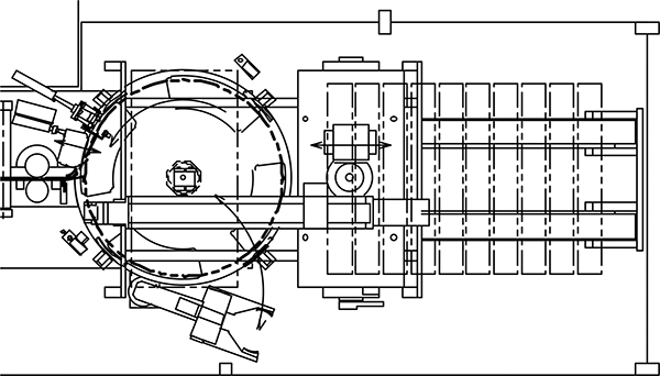
Machine with inlet/outlet stars (Patent Application: 1985.1)
Inlet and outlet stars have been installed on the transfer line to forcibly take out and push out immediately before and after labels are applied to containers to enable stable high-speed application of labels by limiting the pitches and the speed of containers constant (Figures and photos below).
Application star with extension/contraction rollers (Patent Application: 2009.3)
This system enables the all processes of label application, wrapping up, pasting and finishing to be made simultaneously at a high speed within the pressure bonding zone which extends over the length of a label, by means of extension and contraction of the rollers while the container is supported on 3 points: 2 pairs of extension/contraction rollers on the star wheel and the pasting drum.
This system is effective not only for high-speed machines but also for pasting labels on small-diameter containers such as vials and ampules and is adopted in a tack labeler (LKS type) (Figures and photos below).