The company was received a request for a labeler by a pharmaceutical company and started development of a shrink tack labeler that wraps a shrink tack label around an eye drop container or a syringe, allows to heat-shrink to tightly contact to uneven containers.
The first shrink tack labeler was developed for eye drop containers of a pharmaceutical company S and delivered in 1993. The shrink tack label for it covered the whole round body container including the cap and the portion for the cap was tapered. It employed the conventional system that used an application drum and an R finishing plate to apply labels, which then were shrank to make close contact with hot air on the ordinary conveyor belt. Then to meet a request from another pharmaceutical company C, the company developed a shrink tack labeler for syringes for the first time and shipped in 1999. Syringes were transferred in the perpendicularly standing position rotating around the application star wheel, then shrink tack labels were applied to those syringes, hot air was blown to shrink during transfer on the perpendicular conveyor belt.
- Table of Contents
- Establishment of the shrink tack labeler technology
- Technical background of shifting from tape label to sleeve shrink label
- Combined tack labeler machine and peripheral devices
- Combined machine with a tack labeler and a shrink labeler
- Combined machine with a syringe assembler and a tack labeler
- Combined machine of a tack labeler with visual inspection and label application inspection function
- Side/top application tack labeler combined machine and collecting unit
Establishment of the shrink tack labeler technology
A shrink tack labeler for undefined shape eye drop containers with dimples was developed and shipped to a pharmaceutical company S in 2001. The label wrapped the whole body of an undefined shape container and had a “tab” on the top to make peeling-off of the cap label easy. This shrink tack labeler had several challenges difficult to solve.
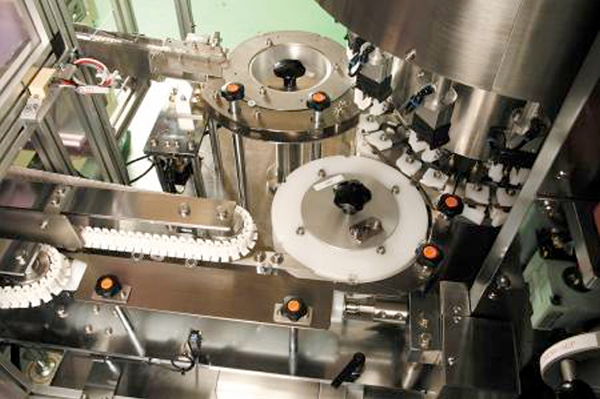
The first challenge was the fact that eye drop containers were not cylindrical round bottle. The second was the label overlapped up to the top surface of the cap. This prevented label application using the conventional method available at that time. To overcome these challenges, it was necessary to insert a hollow bobbin into the undefined shape cap to make a round body portion while the container was being transferred with the turret rotary unit. This was to put a non-adhesive processed bobbin of the same diameter as the container on the irregular shaped head of the container and press the bobbin against it, make the container and the bobbin one-piece, around which a shrink tack label was wrapped around to apply at the application rotary assembly (Photos and diagrams below).
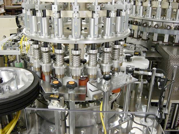
In the following process of the heat shrink rotary assembly, the head of the container is pressed to keep in position with the bobbin removed and hot air is blown to shrink the tack label to fit close to the container (1st photo below).
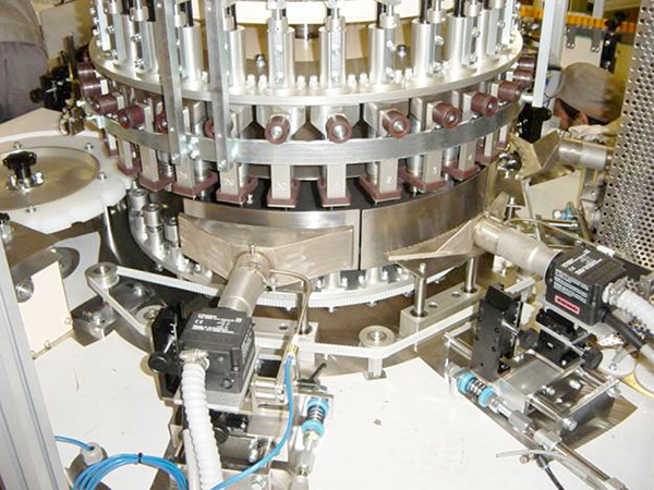
Thirdly, it was necessary to align label directions with the direction of undefined shape containers with dimples. Containers must face in the same direction to apply labels and therefore directions must be limited before application. This problem was solved with the technology of the patent, “Direction limiting unit for lightweight containers with dimples” described before (2nd photo below).
With the completion of this innovative shrink tack labeler, KOYO acquired reliance from our customer company and we delivered six shrink tack labeler machines of the same model to one pharmaceutical manufacturer. This model was also shipped to other domestic pharmaceutical manufacturers as well as those overseas and enjoyed a very favorable reputation.
Technical background of shifting from tape label to sleeve shrink label
The technology employed here has been developed to form a tape label into a sleeve shaped label.
Shrink labelers are originally designed to apply shrink labels preformed to a sleeve shape to containers, and then heated to shrink to close-fit to the shape of the containers. The sleeve shrink labels are considerable more expensive than tape roll labels. Costs for labels which may be tremendous when accumulated can be dramatically reduced by adding a process to form tape labels to sleeve labels to a shrink labeler. Even if a labeler price with such sleeve label forming unit becomes a little higher, the initial cost for purchasing such labeler will be balanced out in a year or so with the accumulated price difference between sleeve labels and tape labels.
The following section shows an overview of the patents related to sleeve label forming.
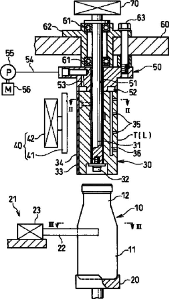
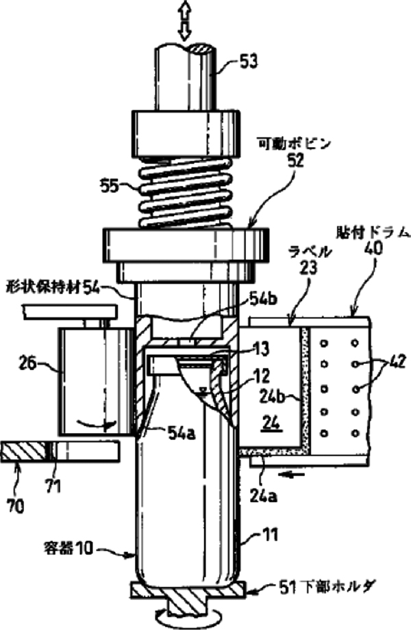
Movable bobbin type sleeve label forming shrink labeler (Patent: 1999.6)
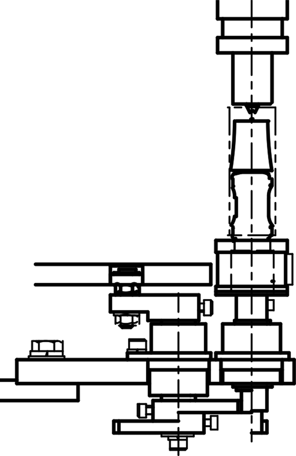
Sleeve shaped shrink labels are formed by inserting the head of a container into the movable bobbin and then a tape label is wrapped around and joined around the bobbin and the container.
Then the sleeve shrink label is held and the movable bobbin is pulled out, then the shrink label is heated to shrink to make it close-fit to the container. This drastically reduces label costs and increases label application speed (Figure 1 below).
Sleeve label forming & insertion unit (Patent Application: 2000.2)
A tape shaped shrink label is wrapped around the forming bobbin and joined to form a sleeve shrink label, which then is lowered to put over a container. Then the label is heated to shrink to close-fit to the container. This drastically reduces label costs and contributes container recycling as well (2nd picture below).
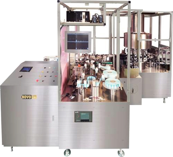
Combined tack labeler machine and peripheral devices
The great shares of tack labelers have gone to pharmaceutical companies in recent years. Lines may be collected for delivery with combined machines of a tack labeler and other units or a tack labeler and peripheral devices. For example, a combined machine with a labeler that applies not only tack labels but also shrink labels or national certificate stamps to containers. And a collection equipment may be installed to arrange and align containers already have tack labels placed and to pack on a tray.
Some combined machines may have a visual inspection unit or a label application inspection unit before and/or after the tack labeler. The next section introduces typical examples.
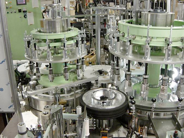
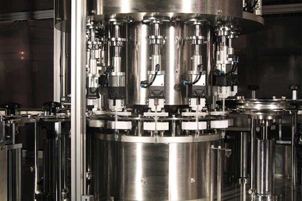
Combined machine with a tack labeler and a shrink labeler
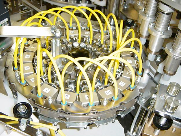
A sleeve shrink label is put over an undefined shape eye drop container, to which hot air is blown to allow it pre-shrink. Tack labels are applied to round body vial bottles. This machine is a multi-purpose combine machine that can apply labels of different specifications for different containers (Photos below).
This type of combined machine can reduce spaces and costs and avoid line control mechanism from becoming complicated compared from manufacturing and installing separate machines.
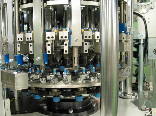
Combined machine with a syringe assembler and a tack labeler
A syringe assembly assembles a syringe by placing a plunger rod into the barrel of a syringe for chemicals, then tightly wrapping to a gasket, and installing a back stop to complete. Each of products is shot after each process with an inspection camera, inspected and any defective products are ejected before labeling. Then the tack labeler applies a label to the barrel of syringes, inspect label application and defective products are discharged. Preparatory process for a syringe assembler has a plunger rod supplier and a back-stop supplier.
By designing and integrating such combined machine that comprises a lot of processes and requires complicated control in terms of both machine and control, space can be minimized as well as effective control is possible by making it systematic. The company’ s combined machines cover major processes before and after labeling in the manufacturing line. The first product of this combine machine was shipped to a pharmaceutical company in January 2009.
Combined machine of a tack labeler with visual inspection and label application inspection function
This machine is a relative large inspection tack labeler combined machine equipped with a system that inspects syringe barrels filled with chemicals in terms of various aspects. Prior to labeling, the combined machine transfers barrels while rotating and revolving them using its visual inspection rotary assembly and inspects the liquid portion, vacant portion and the piston in each barrel using an inspection camera that swings in coordination with the rotation of the barrels. Immediately after a tack label is applied to the barrel, the label application rotary assembly inspect the label application status in the same manner as the visual inspection rotary assembly. And each star wheel shoots the top and side surfaces of caps to inspect using its camera. Good labels are transferred to the line conveyor belt of thenext process and, on the other hand, defective barrels are classified according to their defect types and discharge to the corresponding table.
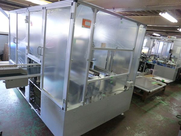
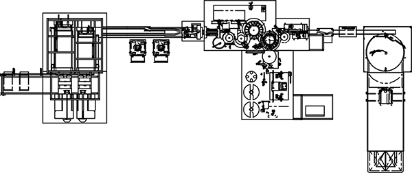
Side/top application tack labeler combined machine and collecting unit
A line where multiple machines are connected via conveyor belts starts with supply of containers, labeling to the side and top surfaces of containers, collecting labeled containers, storing them on trays and ends with the process of carrying-out. Final products, containers that have gone through tack label application and inspection, are transferred to inside the collecting unit, aligned in batches of a certain number, stored on trays and, when ready, carried out on a conveyor (Photos and diagrams below).
Chairman Yamashita has been pre-empting what the society or companies demand, originating technologies that have never seen in the world and sending out new labeling machines. Those labeling machines have generating demands for themselves as machine facilities to be incorporated in production lines that need reduced costs, labor saving and energy saving.
When looking back the company’s history, we have completely changed the whole realm of the labeling machine since the hopper labeler, our origin product, which then advanced to the roll labeler, and then the tack labeler. We also have created a various new technologies and incorporated them in new products to meet demands from our customers: We want to apply innovative design labels to uniquely shaped containers. Based on the principle and the core technologies to which our design always has been sticking as a machine manufacturer, we have been advancing labeler technologies through interaction between various demands from customers and industry-leading technologies. Machine design engineers, machine assembly & adjustment engineers and electric control engineers of the company who have inherited the policy and the technology of Chairman Yamashita, the forerunner of KOYO’s technology, have always introduced and developed new technologies without cease and converted them into actual products. At the adjustment phase of machines before delivery, or at the line operation phase in a local plant with witness by production managers, any information that is obtained through actual machine operation is fedback to machine and electric design departments, where machines and control methods are constantly sophisticated. Needless to say, they have been the main driving force for new technologies. Durability of machines or precision and functionality of machines required for meeting higher quality standards, advancement of machines that become palpable or tangible only under 24 hour-operating conditions can only be resulted from the policy: starting at, returning to, and sticking to the work site.
As we have described so far, the more difficult challenges we face, the simpler and more innovative technologies that make the existing technologies obsolete have been created. In addition, thorough cost reduction sometimes led to high performance products contrary to our expectations. With the advent of an era of revolutionary changes in various fields, we face a pile of challenges never seen before, and all the more the company will keep trying to develop new labeling machines. This is to inherit the “Genealogy of Labeling Machine” of KOYO.