Currently, there is one technology that is employed as a standard for labeling machines both domestic and abroad. We believe KOYO has played a great role in establishing that technology. Then what the KOYO’s technology like or from what kind of idea such technology originated in? This section will track the history of labeling machines from those perspectives.
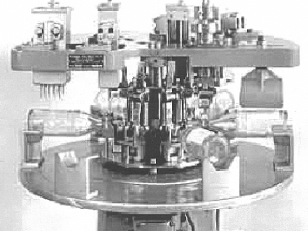
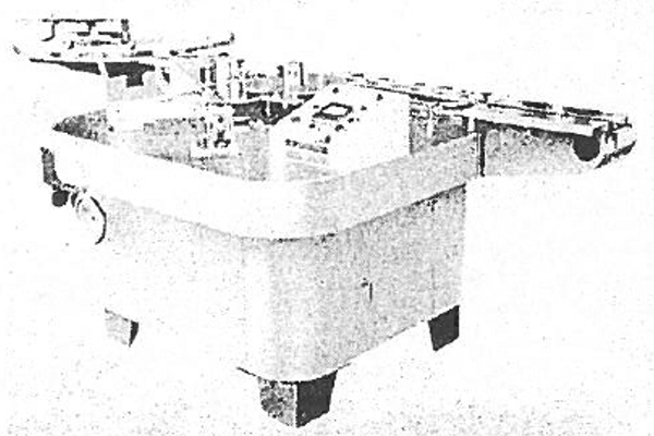
The oldest labeling machine so far as I know is the semi-automatic labeling machine by Krones AG (Germany) made in 1952 (1st photo below). The machine employed a system to lay down containers for placing labels and its production rate was 60 units per minute.
In 1956, Krones AG then developed a full automatic labeling machine whose production rate was 66 units per minute (2nd photo below) and seemed to become widely used rapidly.
Another older labeling machine was that of Jagenberg AG (Germany). A label magazine containing labels was placed on the conveyor line, swing arms catch the label ends and take out, lower them to the conveyor height and paste them to containers by aligning the label position with the center line of the container. There were a lot of technical challenges including an episode; adjusting work to align with the container center was so difficult that it took many months to solve any troubles. In a system that rotates containers to wrap labels around them, the leading edge of the labels was often folded.
In terms of tack labelers, SATO CORPORATION released a hand labeler in 1961 and Takara Pac Ltd. released an auto labeler in 1962.

- Table of Contents
- KOYO labeling machines
- Employment of a vacuum suction drum
- Configuration of a hopper labeler
- Deployment of hopper labelers
- Realization of the hopper labeler (Type LRW) for front/back application of S-character track transferred labels
- Shifting of a hopper labeler to a fixed hopper and its application
KOYO labeling machines
In the midst of such circumstances both domestic and abroad, KOYO Automatic Machine Co., Ltd (founded on January 5, 1968) shipped its first hopper labeler (foliage labeler, Type “LS-80”) to a honey manufacture and sales company on May 9, 1968. It was a challenging project for the company to release a labeling machine that incorporated the world’s first system.
The machine was equipped with all basic features of labeling machines handed down to the present and it is not an overestimate that this machine determined the direction of development of labeling machines. The core technology of this type was to suction paper labels by vacuum, send and pasted them to containers. Until the advent of this model, the vacuum suction system had been believed to be inappropriate for paper labels because of frequent problems of two-label suctioning due to vacuum leaks. Due to this difficulty, the system described earlier had been employed to catch and take out labels from the hopper (magazine) and then paste them.
Employment of a vacuum suction drum
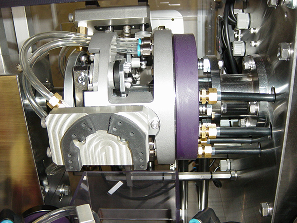
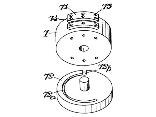
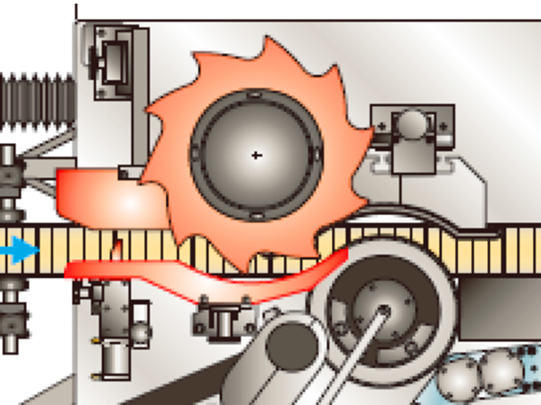
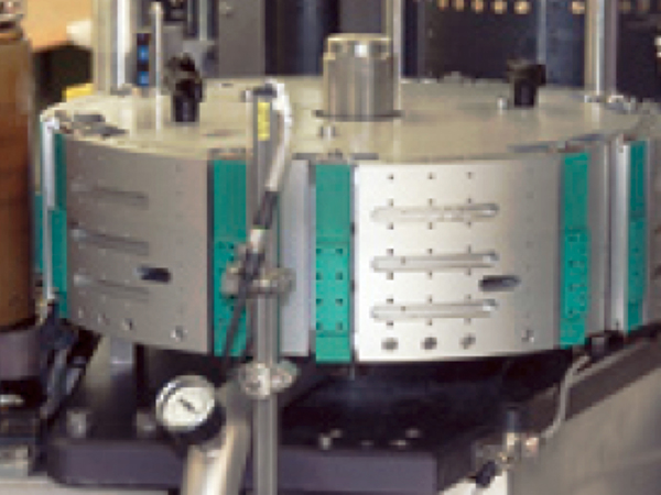
The important decision by KOYO Automatic Machine to employ a suction system for labels using a vacuum pump which was very expensive at that time determined the direction of the development of labeling machines thereafter (Photos and diagrams below). The system invented employed a very simple label suction control system that uses a contact plate and the groove on the rotor board (at first the component was made of gunmetal and fixed type without springs) immediately below the transfer drum.
One of the hard challenges throughout the development process was the method to take out labels one by one from the label hopper (label magazine) where foliage labels (cut labels) are stored.
Delicate operations are necessary in order to take labels held with claws at the take out port on the label hopper smoothly by releasing them off the claws. The mechanism that made this possible was the linkage of a swing hopper that draws a unique track with a cum & link mechanism, and rotation movements of a vacuum suction drum.
This cum & link mechanism draws a trajectory produced by mixing the right and left swinging movement of the crank to the suction drum and the fore and aft swinging movement of the cum. This movement makes the label hopper repeat movement cycles of moving closer to the suction drum until it comes into contact with the drum and then move away from the drum in synchronization with the rotation speed of the drum. More precisely, when the tip of the hopper moves at a slightly higher speed than the rotation of the suction drum, the claws will move off the tip of the labels. At the same time, the portion between the center and the trailing edge of the label will make a positive curvature thus it is separated from the following label (Patent: 1971.12).
Configuration of a hopper labeler
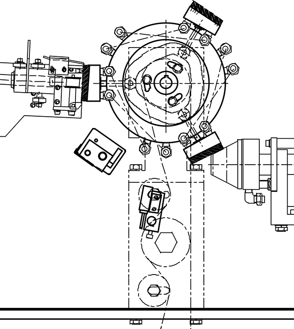
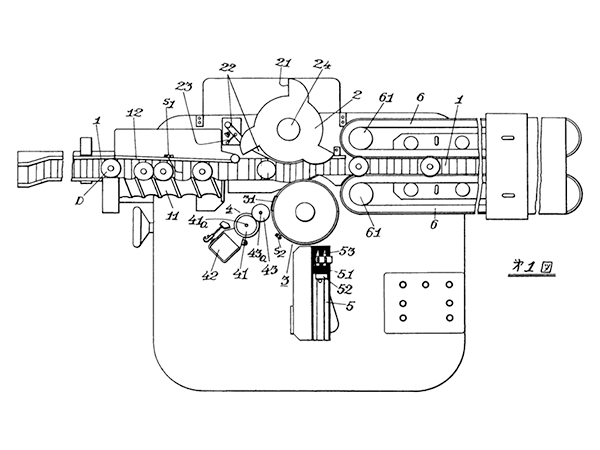
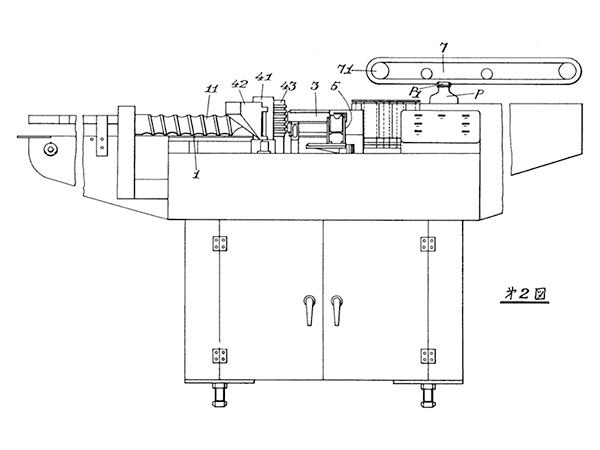
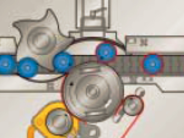
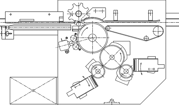
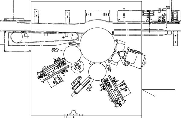
The whole sketch of a one-sheet labeling machine can be seen in several patent documents in 1971 (Diagram below). This machine has almost all of basic elements that are incorporated in the present labeling machines.
The container transfer unit comprises a conveyor, screws, star wheels and a sensor for label takeout container. The label application unit comprises a pasting drum, an adhesive applicator, a label hopper and a pressure bonding plate.
Although this Patent unit does not employ any round finish plates, which will become one of major labeler components, this is because the main purpose of the patent application was the development of a labeling machine that could handle containers made of soft materials. The label finishing unit comprises a finishing belt that completes pasting of a label while rotating containers and an upper belt used for capping containers.
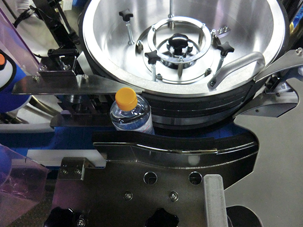
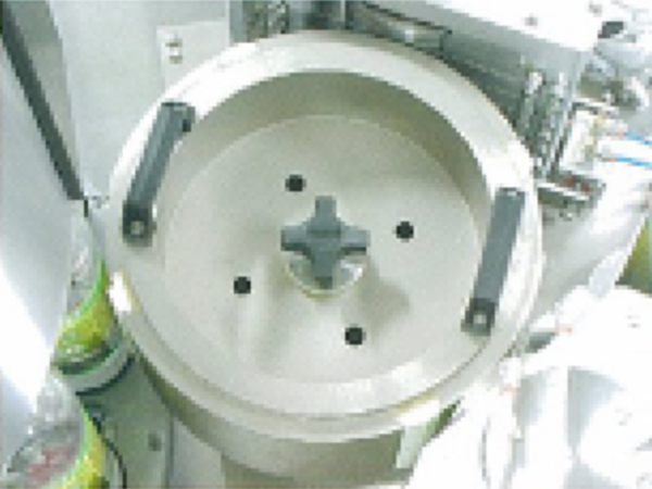
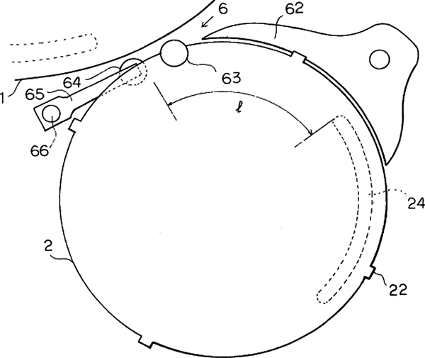
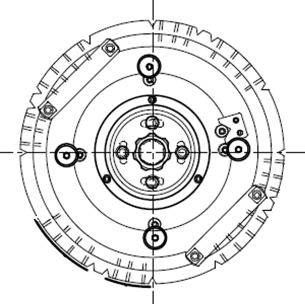
The technique widely used then was to simulate human hand motion to apply a label to a container. Use of a vacuum suction drum to apply labels to a rotating container marked an innovative change. The most important point lied on the extremely simple label application system where the vacuum suction drum rotates and, at the same time, containers rotates and revolves (rotation and revolution) around the drum to wrap and apply labels. The element that enabled this system was the round finish plate (Photos below).
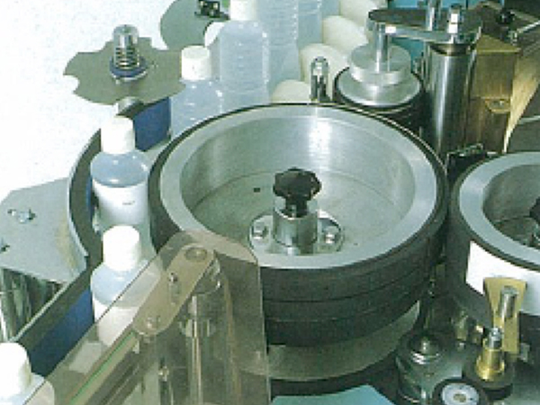
The round finish plate is an arc-shaped pressure bonding plate concentric with the pasting drum and having the size appropriate for the container diameter, and which plates are located in the vicinity of the pasting drum. This round finish plate and the rotating pasting drum work together to rotate containers (rotation and revolution around the drum) (initial rotation) and, at the same speed, labels will be wrapped around the containers.
In addition, a cold glue applicator, a timing screw, a finishing belt and other basic elements of a labeler which later developed to the present models are equipped in an almost perfect forms. Although any patent documents that describe adhesive applicators in detail are not found, the basic configuration of the present models is the same (Patent: 1971.11).
This suction drum type labeling application system employing the configuration above has become the basic model of labeling machines all over the world. The design has disseminated not only throughout Japan but also among a lot of companies around world which fact indicates the model is the global standard of labeling machines.
And the vacuum suction pasting drum that transfers cut labels for the roll labeler that will be later developed is currently employed in all roll labelers in the world (Figures and photos below).
Deployment of hopper labelers
In the course of the deployment of hopper labelers in the following period, the company predicted market needs and improved the speed (improvement of the pasting efficiency), multi-point pasting (front label, back label, shoulder label) and pasting precision and developed new technologies. As described earlier, the hopper labeler has a mechanism to take out labels with the vacuum suction drum in combination with the unique swinging motions of the hopper. As a result, the label take-out capability is limited and the pasting efficiency was about 180 per minute at most.
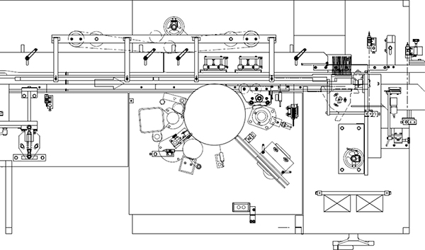
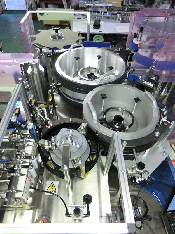
The company increased this processing efficiency by developing a double- hopper labeler [Type LK-300] (Pasting capability 356 units/min.) that doubled the label pasting capability by installing 2 pairs of label hoppers and suction drums and enabling to transfer to the pasting drums alternately (Photos and diagrams below).
In addition to the improved process speed with the double-hopper labeler, a label position correction unit was born for a higher pasting precision (Patent: 1978.10). This patent document describes the double-hopper labeler equipped with 2 pairs of label hoppers and suction drums (Figure below).
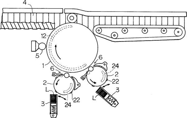
The system has enabled a high-speed supply of labels with double hoppers by making a gap between the suction drum and the pasting drum so that labels will be transferred to the pasting drum that rotates at a peripheral speed faster than that of the suction drum. Reference to a label position correction unit appeared for the first time in this document.
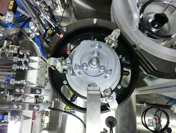
The role of the label position correction unit is, as its name suggests, to improve pasting precision by correcting the label position in the up, down, right and left directions while those labels taken out of the label hopper is rotated and transferred with the suction drum. What has enabled this were the simple mechanism of the correction guide, the correction claws on the suction drum, and vacuum suction opening/closing with the rotor board of the suction drum and their and well-designed linkage operation.
Realization of the hopper labeler (Type LRW) for front/back application of S-character track transferred labels
pasting drums. The front label suction assembly and the back label suction assembly whose pitches are aligned are equipped on the pasting drum, which suctions front and back labels, transfer them and paste on containers (
Figure below). The company shipped its first LFB type labeler in June, 1974.
In 1971, the company developed a National Certificate Stamp Applicator “LK-KO” (Figure below) and 5 units were shipped in that fiscal year alone. Various ideas were incorporated in this model not to waste any single certificate stamp and this model has acquired high confidence and, although the number is not limited, have been shipped every year constantly.
In case of an overlapping label problem, the system is equipped with a two-fold checking mechanism comprising a two-label drum, a collecting comb, and the unit on the collection box to collect certificate stamps and detection on the two overlapping label sensor. Although the label applicator with adhesive to containers (cartons) (Patent: 1977.8, U.S. Patent 1978) was not originally designed to apply certificate stamps to containers (cartons), this system in the present labelers may be applied to certificate stamp applicators. This system applies adhesives to containers and then pastes labels to the bonding surface of the containers. The system eliminates needs for a comb-shaped label peeler, enables front application of labels and allows use of a strong adhesive (such as hot melt).
As described above, the models of hopper labelers have been added with a swing hopper cum link mechanism, a vacuum suction drum and other functions to increase the application precision, two-point application of front/back sides, and increase in the application speed for the 10 years since the foundation of the company. All models of all hopper labelers currently being produced have been developed and shipped during this period. The models include: “LS”, “LN-305”, “LK-300 (double-hopper high speed model)”, “LK-KO (certificate stamp applicator)”, “LRW (S-character transfer front/back side applicator)”, “LFB (double-hopper front/back application drum type)”, “LNO” and a hopper labeler for cassettes (applied model of LRW).
Then the hopper labeler that uses production lines as they are developed into a model to which two or more hopper labeler application stations were connected by adding a container transfer assembly comprising a turret rotary and infeed/outfeed star wheels.
In 1984, the first LH type turret hopper labeler was shipped to a major food company. This product is also utilized in combinations with stations for other application models (roll labeler: LR type, tack labeler: LE type and LK type).
Shifting of a hopper labeler to a fixed hopper and its application
As described earlier, hopper labelers carry out unique swing operation to take out labels out of the hopper with the rotating vacuum suction drum. As a result, labels cannot be refilled to the hopper during operation.
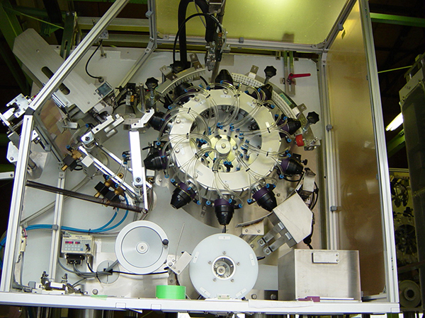
The weight of a hopper for storing larger labels will be large and the label take-out speed will low. In 2000s, development of a new mechanism was started to supply labels without moving the label hopper, which had been a technical challenge (Figure below).
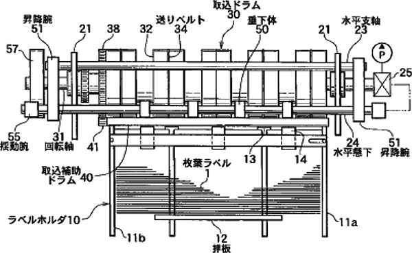
The company developed a take-out mechanism that employs a vacuum suctioning arm to take out labels out of a fixed hopper to accept horizontally long foliage labels and its prototype was completed (Patent Application: 2004.3).
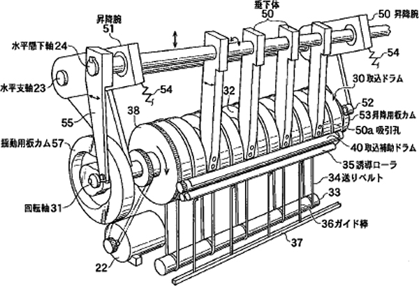
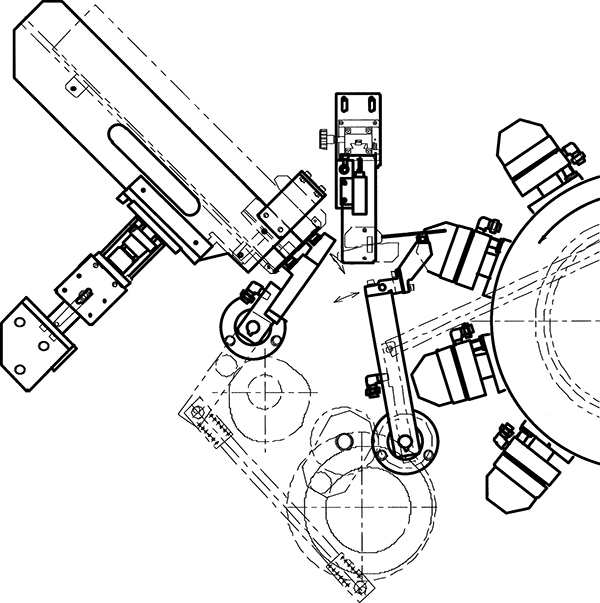
In this mechanism, the suction arm swings to take out foliage labels out of the fixed hopper and allow them to be suctioned on the drum with the take-in auxiliary roller. Immediately after this process, the suction drum will feed the labels, which then will be caught and transferred between the infeed belts. This process enables to take out and supply horizontally long foliage labels reliably. The first mechanism was improved in several phases to be installed in labelers for shipping. This mechanism was further improved so that a cum rotated in response to the continuous rotation of the main unit swings a suction arm in a combined motion in fore and aft and right and left directions, which arm suctions and takes out foliage labels stored in the fixed hopper (Photos and diagrams below).
The suction arm takes out labels by releasing them off the hopper claw in a similar motion to that of the conventional swing hopper. This system was incorporated in large rotary turret labelers that also had the functions of a roll labeler and the products were shipped in five to six units consecutively.
The system was also incorporated in fixed hopper labelers for supplying horizontally long labels or necker labelers for bottle neck labels (Photos and diagrams below).
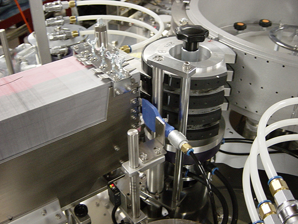
And several prototypes were produced with a shape similar to conventional suction drums not the arm type and a mechanism was established to use an extendable suction head to take out labels out of the fixed hopper (Patent Application: 2007.2).
The extendable suction head installed on the suction drum that rotates intermittently takes out precut labels stored in the fixed hopper by suctioning them while the suction drum is stopped (Figures and photos below).
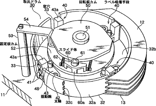
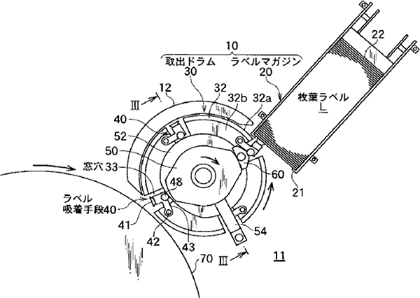
The hopper is fixed and labels can be replenished during operation as well as the number of labels to store can be greatly increased by employing a larger label hopper.
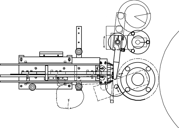
This fixed hopper label supplying unit had come to be installed on a machine that is a dual function machine that can also be used as a roll labeler. There is a mechanism similar to this type suctions and takes out precut labels stored in a fixed hopper using intermittent rotation of the suction drum with a servo motor, and extension/contraction of the uction head using a rotation groove cum (
Photos and diagrams below). This method is applied to necker labelers for neck labels for containers. The system’s role is to rotate and transfers neck labels taken out of the necker hopper by suctioning and transfer those labels to the cone-shaped forming head of the forming drum.