Already back in 1980, a lot of manufacturers had taken part in the tack labeler field and that type of labeler had been established as a standard labeling machine. The system of them is to apply tack labels directly to containers from the peeling unit that peel labels off the base paper and products with that system were called as a hand tack labeler or a unit tack labeler. Label supply or transfer of containers are intermittent processes and their application precision or production capacity were not so high. Development of a tack labeler was demanded to be incorporated in a full-scale production line under such circumstances.
The company was engaged in development work while seeking for a way to utilize the roll labeler technologies then available. In 1982, the first machine was shipped, which marked an advancement in the tack labeler field. The system of that comprised the “Continuous label infeed system” which peels tack labels off and the “Vacuum suction drum” which suctions and rotates for transferring labels to paste them to containers. The system drastically improved the label application precision and speed. With the development of this product, in addition to the hopper labeler and the roll labeler, all major labeler types were present.
Tack labelers grew to be one of the main labeler models with the introduction or incorporation of a variety of new technologies as well as new functions.
- Table of Contents
- Why a drum is needed to apply labels?
- Continuous infeed tack labelers (LR-**T)
- Patents related to the tack label
- Establishment of continuous infeed and shifting to the intermittent infeed tack labeler
- Improvement of the functions of continuous infeed tack labeler
- Shifting to an intermittent infeed tack labeler (LK type & LKS type)
- Advancement of other comprising elements: With a focus on the relationships with tack labelers
- Application star wheel
- Application star wheel with an extension/contraction roller
- Supply unit for unstable containers
- Transfer of objects that are difficult to hold perpendicular
- Lifting and lowering device on the label supply assembly (Patent: 1995.3)
-
Container direction limiting unit
- Star cam arm type direction limiting unit for containers with a handle (Patent Application: 1983.9)
- Direction limiting turret for containers with a handle (Patent: 1993.7)
- Direction limiting unit for lightweight containers with dimples (Patent Application: 2001.5)
- Direction limitation of containers with a handle in a conveyor belt line (Working example)
-
Error label removal unit
- Comb type error label removal unit (Patent: 1988.11)
- Base paper take-up type error label removal unit (Patent Application: 2005.12)
- Comb type error label discharge unit with a roller (Patent Application: 2007.7)
- Belt type error label discharge unit for tack labels (equipped with the present tack labeler models)
Why a drum is needed to apply labels?
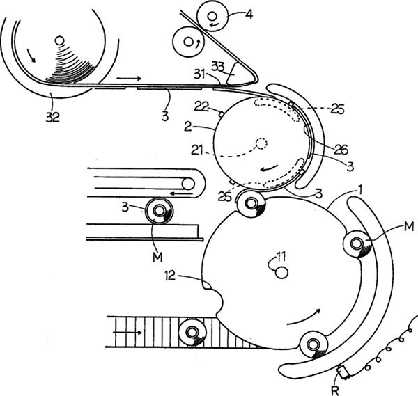
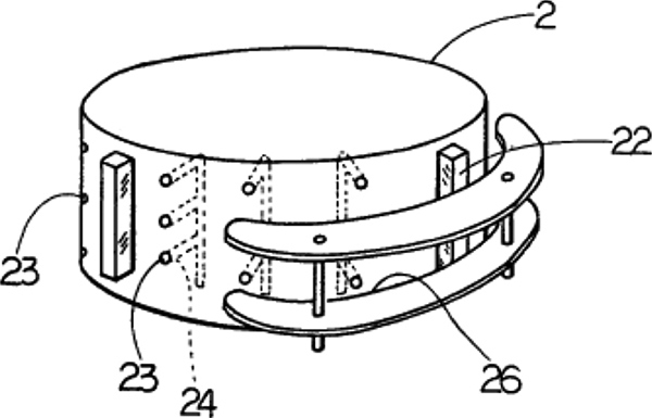
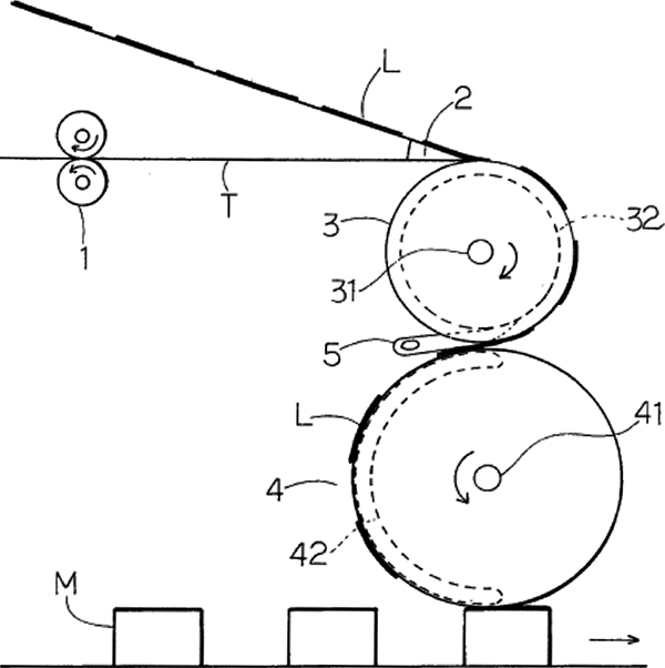
Conventional tack labelers were able to paste labels directly to containers. Why trouble was taken to employ a drum to paste labels? You may think incorporating a drum would lead to increased costs. Now we are going to review how effective a drum is for tack labelers. The label peel-off guide is installed close enough to but not be in contact with the drum periphery surface (Figure below).
Labels sent out with the label peel-off guide will be instantly vacuum-suctioned to the periphery surface of the rotating drum while being kept on the base paper. This minimizes time when one end of a label remains free in the air.
Let us explore the details of tack labeler transfer processes. The leading edge of a peeled label will immediately be suctioned to the vacuum suction port at the side periphery surface of the drum to be kept in place while the trailing edge remains sticking on the base paper. The fore and aft edges of the label are secured and the whole label is kept in the stable state. As peeling-off of a label proceeds, the area vacuum-suctioned at the side periphery surface of the drum increases so that the label will come off the base paper on the peel-off guide while keeping the stable state. Then the drum will rotate to transfer the label whose suctioned state is maintained, the label will be applied while the drum holds down the container.
As we have seen, the system does not allow any interference that might make label postures unstable throughout the processes from peeling-off to pasting. On the other hand, in a system where a label will be applied to a container immediately after it is peeled off, an unstable state when the end of the label is free will be generated. In such a state, the application precision of labels may be compromised from disturbances in their posture or depending on the shape of containers.
Label application with a drum is made with a constant speed rotation motion, irrespective of whether labels are peeled-off in continuous label infeed or intermittent label infeed, and, therefore, it is possible to increase label application speed.
In terms of the application capability of tack labelers, the continuous label infeed peel-off system is higher than the intermittent label infeed pee-off system.
Continuous infeed tack labelers (LR-**T)
Development of a tack labeler of the continuous label infeed system started in around 1980 and a series of patents related to the tack labelers followed. In the same year (1982) the company shipped the No.1 continuous infeed roll labeler (LR model), the company delivered its first continuous infeed tack labeler to an audio equipment manufacturer.
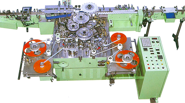
The following section shows an overview of the patents related to the tack labeler (Figures and photos below).
Patents related to the tack label
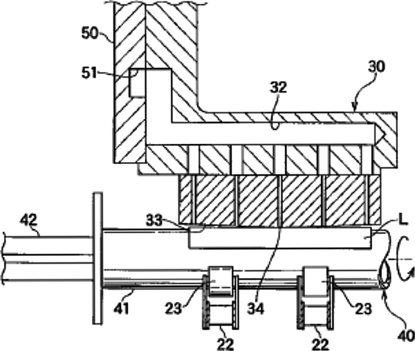
The first tack labeler model comprised a label peel-off unit, an application drum and an application star wheel. The model enabled high-speed and highly precise label application capable of supporting continuous transfer of containers with the tack label supply function using continuous infeed as well as an application drum with a label position correction function. (Patent Application: 1981.11, Figure below).
In addition, a heating unit installed on the side of the application drum heats tack labels, activates to soften adhesives and softens tack labels themselves. Warping of tack labels can be prevented by assuring a constant adherence property in all seasons including summer and winter (Patent Application: 1981.12, Figure below).
The next model has a transfer drum installed between the label peel-off unit and the application drum.
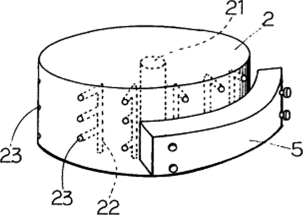
The adhesive side of tack labels is pasted onto the transfer drum, and the tack labels are peeled off from the transfer drum with the peel-off guide to transfer them to the application drum. This eliminates possibility that transfer errors to the application drum even if labels are peeled-off at a high speed (Patent: 1982.7, Figure below).Also, printing on the top surface of tack labels on the transfer drum after peeling-off makes tack label management easier (Patent Application: 1982.7, Figure below).
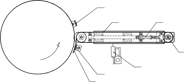
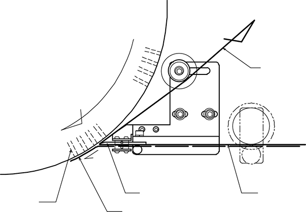
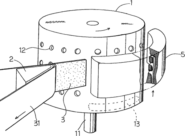
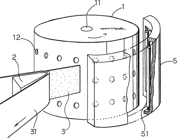
Issues related to transfer of tack labels on the drum have been solved one after another. By blowing air from the transfer guide to the label adhesive surface, it is prevented the adhesive surface from coming into contact with the guide and cause jamming (Patent Application: 1983.2, Figure 1 below).
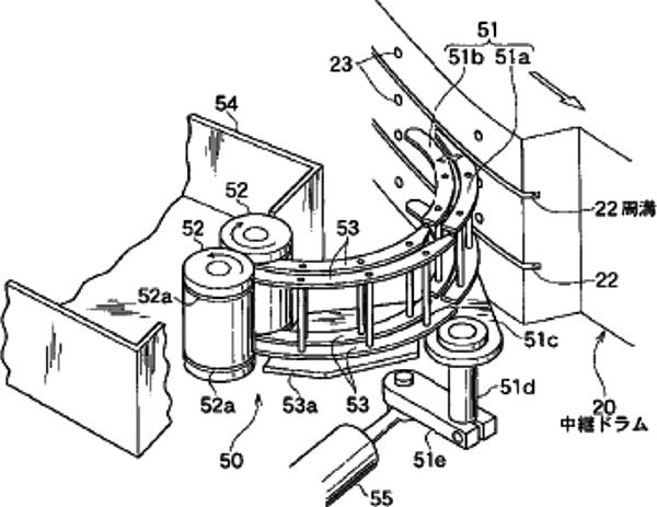
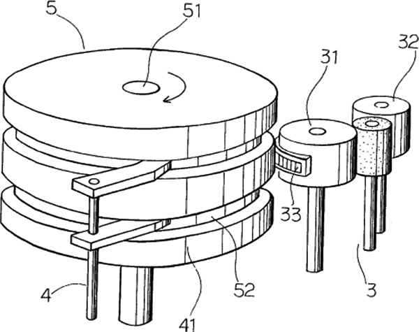
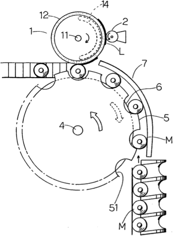
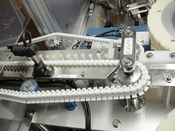
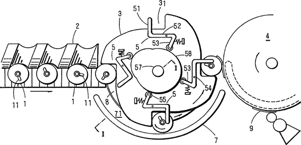
Tack labels are transferred being guided with a lot of non-adhesive processed rollers (51) laid out in parallel with the suction drum. This prevents jamming, folding or warping of labels to enable high-speed transfer of tack labels (Patent Application: 1983.3, 2nd picture below).
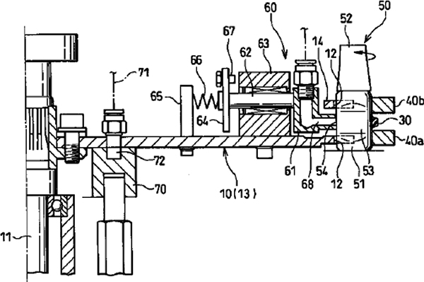
As another configuration, a cleaning unit (81) was installed at the tack label correction drum (5) to automatically remove any adhesives that may stick to the rotation disk (8) on the floor. This eliminates waste labels and needs for works for removing adhesives (Patent: 1983.8, Figure 1 below). A tack labeler incorporating an incision process was proposed (Patent Application: 1983.12, 2nd picture below).
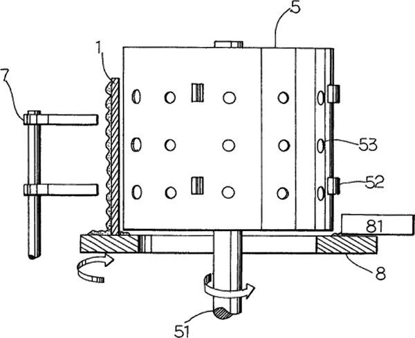

A cutter (3) makes an incision to uncut tack labels on the base paper immediately before they are peeled off and the labeler pastes those tack labels to containers while the base paper is wound up and collected. This system eliminates the punching process from the manufacturing processes for tack labels thus reduces costs.
As described above, the company was slow in taking part in the tack labeler field and utilized its proprietary systems suchas a vacuum suction drum or a continuous label infeed peel-off system to improve the precision and speed of label application.
Our products developed further to be a multi-functional, universal labeling machine equipped with a printing unit, a printing inspection function or a rejection unit for error labels. A transfer method and a pasting method were devised to process for the specific shapes of containers. For objects which are difficult to transfer or labeling such as ampules or syringes for example, the company defined methods to supply, transfer and pasting labels
Establishment of continuous infeed and shifting to the intermittent infeed tack labeler
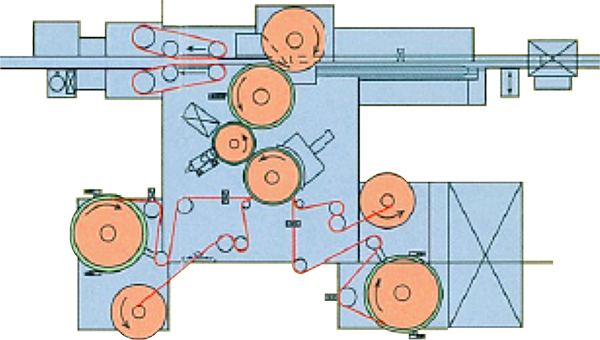
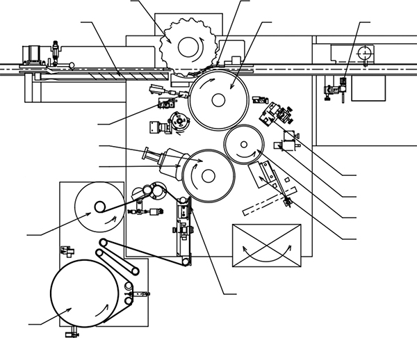
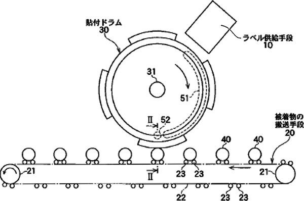
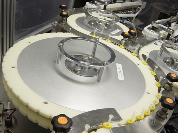
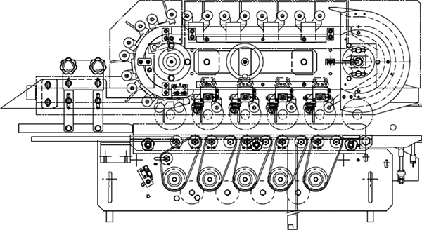
The company carried on shifting to a higher speed tack labeler with the continuous infeed function based on the roll labeler technologies and completed a perfect continuous infeed system (Working example in 2002). The system employed and utilized suction type transferdrums: correction drum, printing drum and application drum (Figures and photos below).
Improvement of the functions of continuous infeed tack labeler
Continuous infeed tack labeler can be equipped with a variety of functions that meet high quality requirements by pharmaceutical companies. This system can also meet demands by customers flexibly. Various models of printing units can be installed in this type including but not limited to an ink jet printer or a laser marker. Another system had versatile functions to carry out and manage printing inspection, discharging error labels or label application inspection.
Shifting to an intermittent infeed tack labeler (LK type & LKS type)
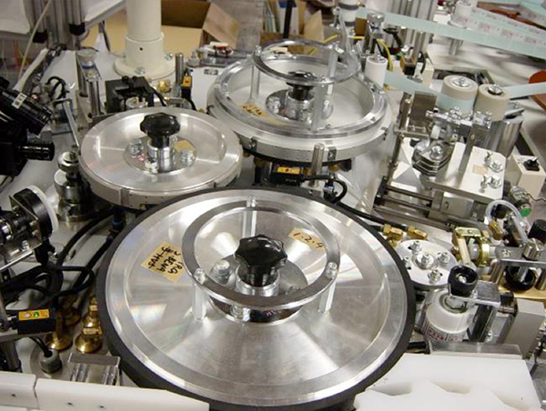
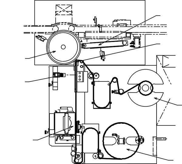
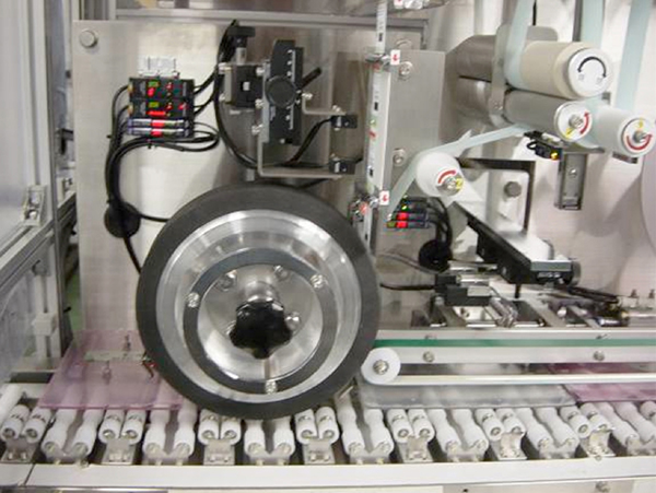
With the development of servo motors and control systems, highly precise intermittent label infeed came to be feasible. Shifting to the intermittent label infeed system was proceeded with aiming to make tack labelers more compact and to reduce costs (Figures and photos below).

What are advantages to switch label infeed system from continuous to intermittent?
The continuous infeed system has a correction drum and a printing drum, which requires more space and costs. The intermittent infeed system, on the contrary, is able to peel off and send labels in coordination with the movement of the periphery surface of the application drum and tack labels can be transferred to the specified position on the application drum precisely. Only an application drum is used as the vacuum suction type drum making the whole machine compact.
It can also be equipped with a hot printer or a thermal printer that can make printing even when the whole unit is in the stop mode. And a supplementary infeed unit as a label buffer unit can be installed instead of the tension roller that accompanies with the label table.
We have also improved the base paper take-up table to be more user-friendly and convenient by installing a new label table developed for roll labelers. The company manufactured our proprietary label infeed control unit from its substrates and our original intermittent label infeed control software Photos below).
This control unit has led to high precision label infeed control, which has contributed to increase in label application precision. The establishment of standards in terms of both hardware and software aspects in control resulted in reduced costs for the control unit itself as well as reduction in work processes such as electrical designs and ladder creation. This intermittent infeed tack labeler is resulted from such improvement in terms of hardware and software for both machine units and control units.
Quality requirements by pharmaceutical companies are becoming more and more complicated and stringent, which requires multi phased validation works and the performance of both hardware and software must be improved. For the implementation of such improvements, it is important to strengthen human networks such as linkage among sales representatives, machine or electric design engineers, machine technicians, and control engineers.
Advancement of other comprising elements: With a focus on the relationships with tack labelers
We have described mainly on the advancement of label infeed/ supply units in the previous sections.
Now we are going to introduce some of pasting methods, container supply/ transfer units, other comprising elements of labelers by putting emphasis on the technologies related to tack labelers. Many of those technologies are, of course, applicable to hopper labelers and roll labelers as well.
Application star wheel
For smaller containers such as syringes, ampules or vial bottles, a system to apply labels while containers are transferred rotating around a star wheel. The concept of establishing labeling processes with a series of rotations (revolution and rotation) is employed in this system as well.
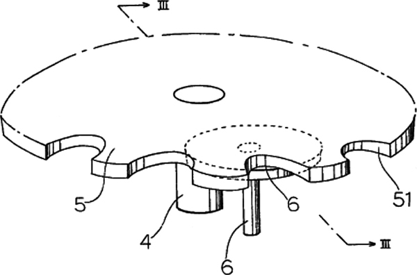
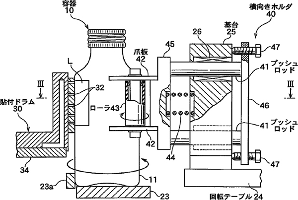
Let us overview the process of its development in terms of the patents. The prototype of that model is indicated in the patent application document (”Star wheel with a driving large pressure roller” [1982.9, Figure 1 below]) in 1982 when the No.1 tack labeler was shipped. A pressure roller (6) concentric with the star wheel is installed exposed inside the application star wheel (5) and containers will be kept between the application drum (1) and the pressure roller and forced to rotate for label application. This system can prevent free slipping or warping of labels. Smooth application of labels free of friction resistance is possible since there is no contact with the pocket of the star wheel and the configuration is not held with other rollers.
The company also devised a model non-concentric with the application star wheel by reducing the size of the pressure roller with a driving source (Patent: 1982.12, 2nd picture below). Then the company completed a model that can wraps label saround containers simply by rotating the application drum without having to drive the pressure roller (Patent: 1983.3, 3rd picture below). A free pressure roller (6) is installed in the exposed state inside the application star wheel (5), containers are held between the application drum and the pressure roller and rotated in any mode to paste labels. Its structure is rather simple, it does not require any control of rotation speeds and adjustment is easy.
In the patent of “Mountain type periphery surface application drum” (2006.6, Figure below), a method to apply labels to small containers such as syringes transferred on two free rollers in the laid-down state is described, although these free rollers are not of an application star wheel. The main feature of this patent is to make the periphery surface of the application drum to a mountain shaped periphery surface so that labels can be pasted neatly free of wrinkles even if containers of uneven shapes are included.
Application star wheel with an extension/contraction roller
After having followed these processes, the label application system using a star wheel was perfected when the patent “Application star wheel with an extension/contraction roller” (March 2009,
Figure below) was granted.
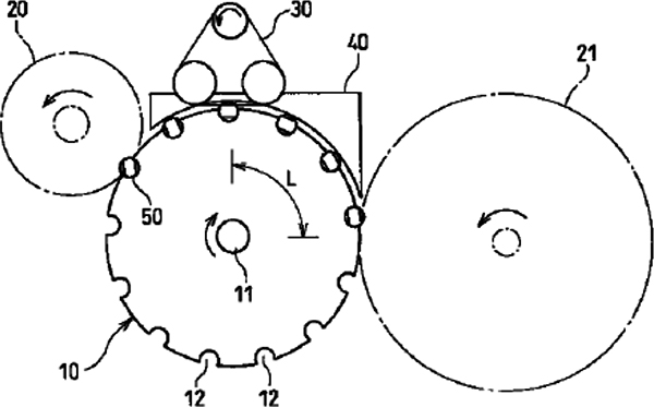
The product has multiple pairs of extendable/contractible container holding rollers on the application star wheel, which hold containers together with the application drum at three lines during application. The rollers extend and contract to press containers to the application drum serially to carry out application and finishing of labels simultaneously. Contacts with containers are made in lines at three points ensures superb perpendicularity even while containers are rotating at a high speed and thus enables precise label application. This application system is based upon the same concept as the system that uses a drum and an R finishing plate. Containers will rotate and revolve at the same time in synchronization with the rotation of the application drum to apply, wrap around labels and finish application process.
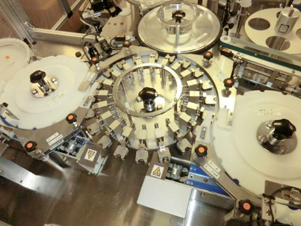
Based on the similar approach, various mechanisms have been devised for the label application system using a turret rotary function. This system was, as described in the sections, “The Development and Advancement of Roll Labelers”, developed as a high-speed label application system for roll labelers for applying labels to smaller containers such as health drink bottles. The system was employed in a tack labeler (LKS model) to apply labels at a high precision and at a relatively high speed to even smaller containers such as vial bottles (Photos below).
Supply unit for unstable containers
Unstable containers such as ampules or vial bottles (filled with injection chemical) often fall during supply and transfer, each time the machines had to stop for correcting them upright. This caused compromised production efficiency and demands arose for a new supply and transfer method that prevent containers from falling.
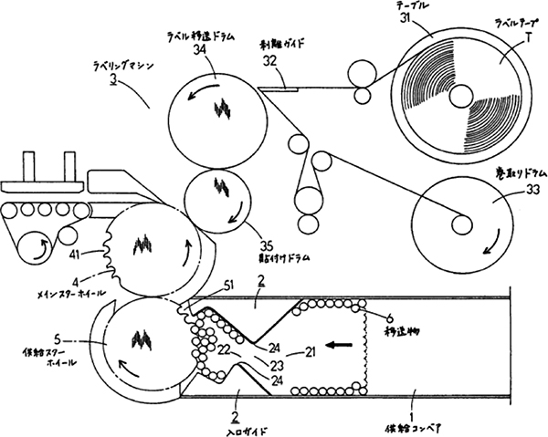
Container supply conveyor with a return guide and a supply star wheel (Patent: 1986.9)
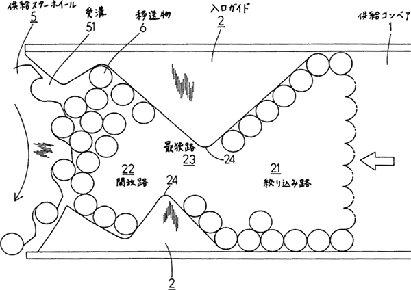
In a container supply unit where a container supplying conveyor belt and a star wheel are placed in the downstream side of that belt, a return guide is installed comprising a “narrowing route” that narrows supply area gradually and a “widening route” that broadens supply area gradually (Figure below).
This configuration prevents containers from falling or jamming and enables smooth transfer of containers.
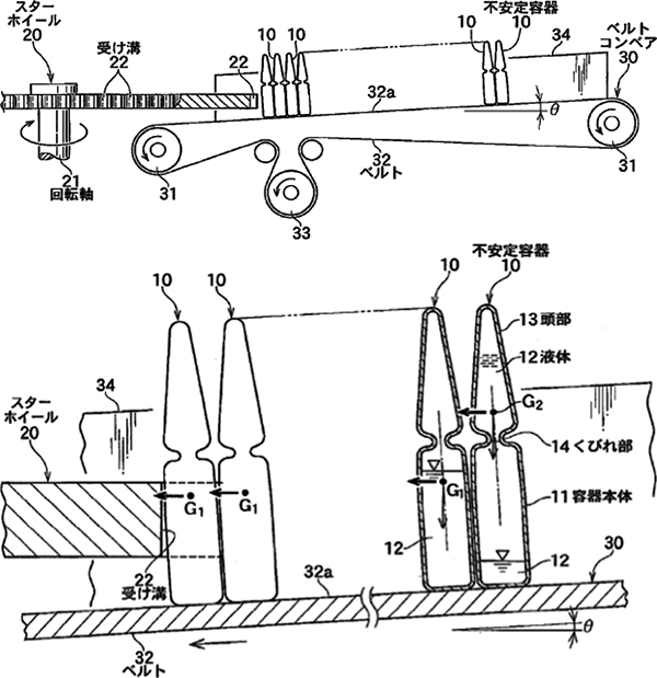
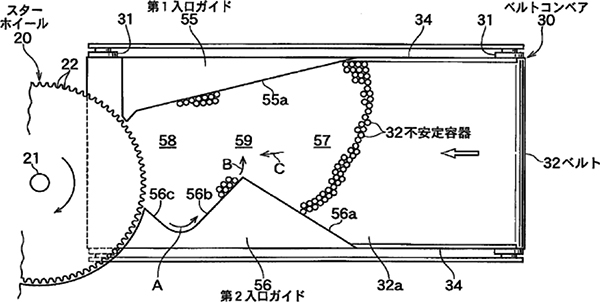
Supply unit for unstable containers, an inclined supply conveyor belt and a supply star wheel (Patent: 2009.1)
In a container supply unit where a container supplying conveyor belt and a star wheel are placed in the downstream side of that belt, the transfer surface of the conveyor belt is inclined descending toward the star wheel so that unstable containers will be transferred in the inclined position toward the star wheel (Figure below). This prevents unstable containers from falling and can transfer them without troubles. By installing a uniquely shaped return guide on the container supply conveyor belt to prevent containers returning to the back side of the belt from falling. This system was resulted from efforts to observe actual transfer on a conveyor belt and thought of a method to prevent jamming or falling of containers.
This shape was realized only after observing a lot of ampules flew like a fluid and having understood the characteristics of such motion. The idea to incline the supply conveyor descending to the advancing direction, was born from a reverse thinking to incline ampules whose weight center is at a higher position and easy to fall will prevent them from falling further. It is impossible for ampules leaning on the star wheel in the transfer direction to fall. These two elements made supply of containers dramatically smooth and labeling efficiency for unstable containers was improved.
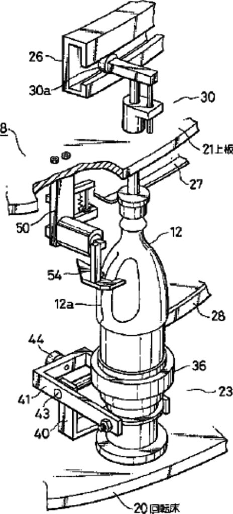
Transfer of objects that are difficult to hold perpendicular
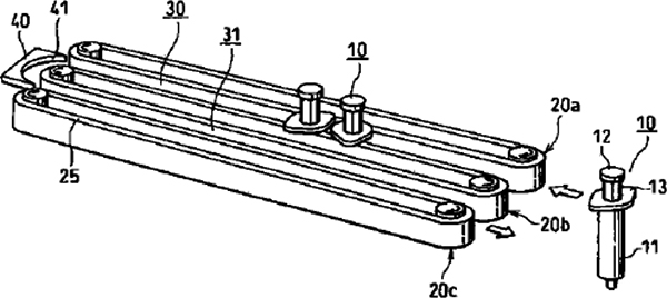
Several transfer techniques to carry objects that are difficult to hold perpendicular such as syringes have been adopted and utilized in actual machines. One example is a system to transfer in a straight way by two lines of conveyor belts installed perpendicular over which protruding parts of objects to t ransfer are hooked and transferred being suspended perpendicular (Patent Application: 1998.10, Figures and photos below).
Some shrink tack labelers blow hot air to shrink tack labels pasted on syringes to shrink. A method is also employed to hook protruding part of objects on the star wheel pocket to transfer while rotating (1st photo below).
Another method is, as described earlier, syringes are laid down on 2 free rollers to carry and to subject to label application (2nd photo below). Syringes on the rollers come in contact with the application drum of the upright tack labeler, are pressed, rotate with the rotation of the application drum to apply labels to them.
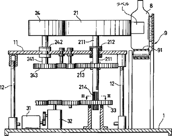
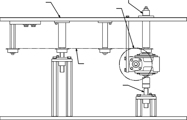
Lifting and lowering device on the label supply assembly (Patent: 1995.3)
The top board at the supply assembly can be lifted or lowered by turning the screw axis that supports the top board to change application height of labels (Figure below).This makes changing label application height easy when switching over product types.
While demands for machines commonly available for multiple product types are increasing, this mechanism was adopted in a lot of machine types (tack labeler, hopper labeler, and roll labeler) and its share in the shipped products has been increasing in recent years. In particular, almost all LKS and LK tack labelers in recent years have this mechanism.
Container direction limiting unit
This unit has been developed to align containers with a handle or undefined shaped containers in a certain direction so that the application position of labels can be limited to the predetermined area. Its overview is shown in the following sections.
Star cam arm type direction limiting unit for containers with a handle (Patent Application: 1983.9)
The pocket assembly of the star wheel transfers containers with a handle while allowing them to rotate until the correction arm that limits container rotation protrudes into the pocket assembly to stop the rotation of containers (Figure 1 below).
This enables to apply labels to the predetermined position of containers with a handle. Conventional complex units that use photoelectric tubes are not necessary any more.
Direction limiting turret for containers with a handle (Patent: 1993.7)
In a turret rotary system, containers with a handle on the base cup is rotated driven by a belt, rotation of the containers is stopped with the direction limiting plate’s protrusion, the direction of the container handles is aligned and the application drum applies labels to the containers (2nd picture below).
Direction limitation of containers with a handle is made with this system in the turret rotary system.
Direction limiting unit for lightweight containers with dimples (Patent Application: 2001.5)
The star wheel transfers small, lightweight containers with uneven dimples while forced to rotate with the neighboring correction belt, the dimple at the specified position of containers is suctions with the negative pressure suction assembly to hand them down to the next process (Figure below).
This system is able to limit reliably direction of small, lightweight containers with uneven dimples, which have been regarded as difficult to handle.
Direction limitation of containers with a handle in a conveyor belt line (Working example)
The reverse belt forces containers with a handle to rotate, stop its rotation with protrusion of the direction limiting arm so that the handle positions of the containers are aligned in the specified direction (Figure below).
Error label removal unit
Removing error labels (labels with defective printing or joint lines) before applying labels to containers eliminates needs for discharging containers with error labels applied in later processes. As a result, work processes to discharge containers with error labels or to remove error labels off containers.
Although this unit was used for discharging error labels for roll labelers at first, its concept was applied for tack labelers as well to enable precise label management. Labels with defective printing or wrong labels will not be applied directly to containers and you can confirm the precise number of discharged labels.
This unit has disseminated as the standard unit for tack labelers both in Japan and abroad as indispensable to meet high quality standard required for medical products.
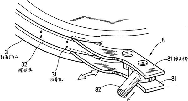
クComb type error label removal unit (Patent: 1988.11)
While labels are transferred with the application drum, the label removal comb moves in and out of the groove in the application drum in response to an error label (labels with defective printing or joint lines) detection signal to remove error labels (Figure 1 below).
This removes error labels before application to containers and the final production inspection only needs for checking whether labels are applied or not.
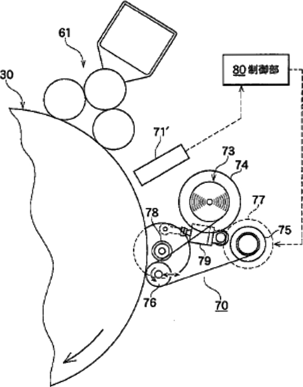
Base paper take-up type error label removal unit (Patent Application: 2005.12)
While labels are transferred with the application drum, the base paper tape, in response to an error label (labels with defective printing or joint lines) detection signal, protrudes toward the application drum and is applied with glue, then the tape contacts an error label to remove (2nd picture below).
Removed error labels are wound up and stored so that precise recording and management of error labels are possible.
Comb type error label discharge unit with a roller (Patent Application: 2007.7)
The label removal combs (inside and outside) move in and out of the groove in the application drum in response to a signal from the sensor to detect error labels to remove an error label, then the peeled-off labels will be forced to be discharged with a pair of rotating discharge rollers (Figure 1 below). This system supports discharge of longer labels.
Belt type error label discharge unit for tack labels (equipped with the present tack labeler models)
By protruding the error label discharge belt to the adhesive surface of tack labels to take them up and discharge (2nd picture below). This system is employed as the standard system for the present tack labelers.